Executive Summary
Since industries use thermo-sensitive devices and processes, they require temperature control tools. Automatic temperature controllers are effective in regulating temperature because they do not require humans to read and make appropriate adjustments. The temperature controller comprises switch controller, thermistor, AC power, AC/DC power, circuit breaker, cooling system, heating system, alarm, bulbs, and cables. Data acquisition card converts analogue signal from the sensor into a digital signal. Setting control temperature at 80°F with 1°F provides 79°F and 81°F control limits, while setting higher alarm limit at 5°F and lower alarm limit at 4°F provides alarm limits.
Background
Temperature control is very important in industries because it optimises processes and protects devices from damage. According to Dai (2008), automatic temperature control improves the functioning of machines in the textile industry. Likewise, automatic control plays an integral role in other industries, which have thermo-sensitive-devices or processes.
Scope
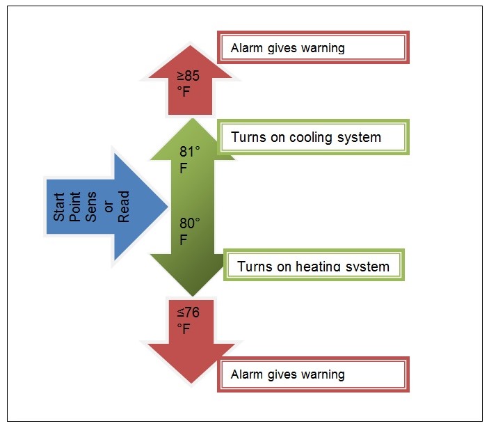
The scope of the project includes the functionality of an automatic temperature controller in industries, which have thermo-sensitive devices and processes. Fundamentally, the report examines the principles of the automatic temperature controller, which has the capacity to maintain temperature at 80°F and give warnings when temperature exceeds 84°F or goes below 77°F.
Design Summary
The design of the project is an experimental study, where the experiment tests the functionality of automatic temperature controller. The experiment involves the capability of thermostat to hold temperature within 80±1°F using three-relay system. Cooling system, heating system, and alarm comprise the three-relays, which collectively regulate temperature of industrial devices.
Unresolved Items
The unresolved item is that there is no automatic circuit breaker to reconnect the circuit once it has broken owing to the high temperature.
Introduction
Measurement of temperature is a common activity in industries. Essentially, temperature is a major factor that influences the integrity of the devices, manufacturing processes, and quality of products (Pimpalgaonkar, Jha, Shukla, & Asthana, 2013). To achieve optimum performance of industrial devices, temperature control is necessary. Moreover, given that some devices are sensitive to high and low temperatures, temperature control is also crucial to protect them from damage. The damage of industrial devices makes companies incur huge losses, which they could have prevented by merely incorporating automatic temperature control devices.
Description of the Project
The project examines automatic temperature controller, which comprises of switch controller, thermistor, circuit breaker, cooling system, heating system, alarm, bulbs, and cables. To regulate temperature within a specific range, the automatic temperature controller has a sensor, which is sensitive to temperature changes. The function of the automatic temperature controller is to control temperature of thermo-sensitive devices within the limited range of 79-81°F. In this view, thermistor is sensitive to slight changes in temperature and accurately measures such a narrow range of temperature. Additionally, the temperature controller has the capability to regulate heating and cooling systems, depending on the prevailing temperature changes.
Implementation
Abstracting the Problem
Temperature control is a common problem that many companies are grappling with in their production plants. Low temperatures reduce production of industrial processes and performance of thermo-sensitive devices, whereas high temperatures damage devices, and hence, make companies incur huge losses (Pushpavanam, 2013). Essentially, temperature influences conductivity of resistors, inductors, capacitors, and semiconductors. According to Paul (2014) modern industrial devices are sensitive to temperature changes because they have electronic chips, which are essential in computerisation. In this view, there is a need to control temperatures of industrial devices within their optimum ranges to optimise production and prevent them from damage.
Division of Tasks
The automatic temperature controller has a number of tasks, which enable it to perform its overall function of regulating temperature. The first task is that the temperature controller must sense the temperature which a device sends as an appropriate digital signal to the temperature switch controller. The second task is that switch controller interprets the digital signal and decides to switch a controller. The switch controller can turn on the heating system, cooling system, or alarm. The third task is that the heating system increases the temperature, the cooling system reduces temperature, or the alarm gives a warning sound.
Problems Faced
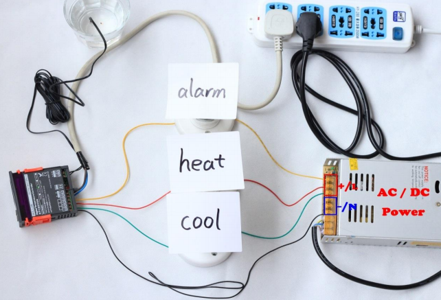
In the connection of the automatic temperature controller, the problems faced relate to the connection of cables, setting of temperature limits, and sensing temperature changes. The temperature controller has five cables, namely, black for AC-power, green for cooling system, yellow for alarm, green for heating system, and white for AC/DC-power, which are confusing when connecting. The setting of temperature limits is a problem because it entails limits for both temperature control and alarm control. Given that temperature of a device varies according to the site of detection, getting the appropriate site was a challenge.
Sensor Selection
Identification of the Sensor Type
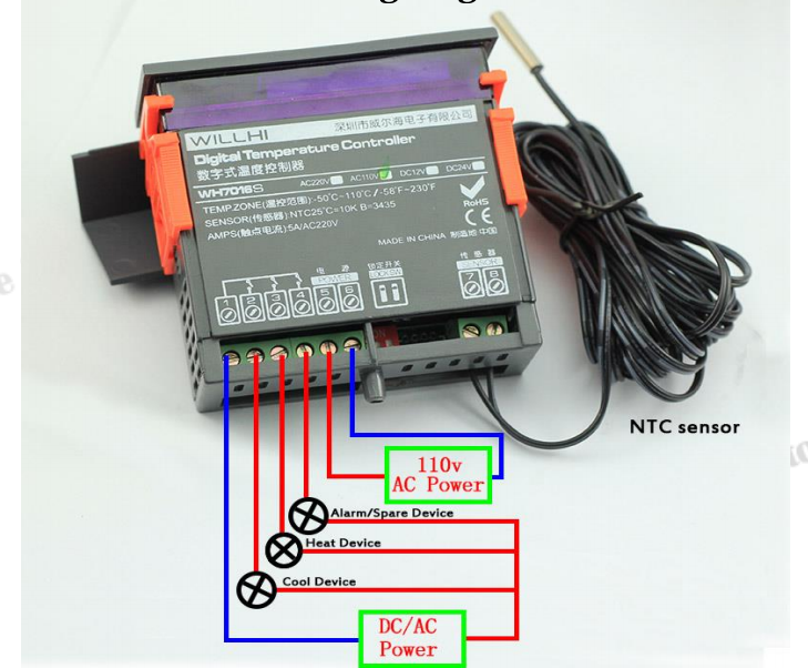
The type of sensor that the temperature controller has is thermistor. Given that the temperature controller is applicable in the regulation of temperature with a narrow range of 79-81°F, the appropriate type of sensor is thermistor. According to Du (2014), thermistor is advantageous in measuring temperature because it is highly sensitive to temperature changes at room temperature and has a relatively high resistance. The high sensitivity of thermistor enhances accuracy of temperature measurements during rapid changes, while relatively high resistance diminishes the occurrence of errors owing to changes in resistance. In this view, since the measurement of the temperature of interest (76-85°F) is close to room temperature (72°F), thermistor is still sensitive within this temperature range. Therefore, the choice of ‘110V Fahrenheit 3-Relay Temperature Controller’ was because it has thermistor sensor and has the capability to regulate temperature via the three-relay system for cooling, heating, and warning.
Performance Test of the Sensor
To test the performance of the sensor, each of the three wires of the switch controller representing the three-relay system was connected to three different bulbs. Shetty and Kolk (2010) state that a sensor has data acquisition card, which converts analogue signals into digital signals. In this case, the sensor was then connected to the switch controller, which receives digital signals. The sensor was set at normal temperature at 80 °F, lower control limit at 79°F, upper control limit at 81°F, upper alarm limit at 85°F, and lower alarm limit at 76°F. The sensor was then held using hands, which is approximately 98°F and the temperature rose quickly. At 81°F, the bulb for cooling system turned on, and continued increase in temperature to 85°F lighted the bulb for alarm and turned on the alarm. When the sensor was placed in cold water, the temperature dropped quickly and at 79°F, the bulb for heating system turned on and continued to drop to 76°F, the alarm gave a warning.
Measurement System Implementation
Hardware Configuration
The hardware configuration of the temperature controller entailed connection of cables to respective terminals on switch controller, sensor, and power. The switch controller requires five cables, which connect it to AC/DC power. The black wire indirectly connects the switch controller to AC power connection through AC/DC power. The green cable connects switch controller to the cooling system, while the red cable connects switch controller to the heating system. The yellow cable connects the switch controller to the alarm, while the white cable connects the switch controller to AC power. In the experiment, cables for heating system, cooling system, and alarm were connected to AC/DC power through the bulbs. Furthermore, the cable for alarm was connected to alarm to give appropriate warning when the temperature reaches 85°F and above or 76°F and below. The hard configuration includes circuit breaker, which shuts down the power whenever the alarm continues to ring and temperature goes high.
Software Configuration
Software configuration of the temperature controller entailed setting of normal temperature and limits for both temperature control and alarm control. First, the temperature control was reset to clear previous settings. Then, the normal temperature (control value) was set at 80°F for the temperature controller to maintain. Since the project expects to maintain temperature within a narrow range of 79°F to 81°F, the temperature controller was set to have a difference (d value) of 1°F, which allowed temperature regulation between 79°F and 81°F. In this case, 79°F is the lowest temperature control limit, while 81°F is the upper temperature control limit. Moreover, the higher temperature alarm was set to have a d value of 5°F, while the lower temperature alarm was set to have a d value of 4°F. The settings of alarm means that the alarm will ring when temperature reaches 85°F and exceeds it or when temperature reaches 76°F and goes below it.
Conclusion
Temperature control is an indispensable activity in an industrial set up because the functioning of devices and outcomes is subject to temperature. The three-relay system enhances automation of the temperature control because it incorporates heating system, cooling system, and warning system in the sensor. Thermistor, which is a sensor that is very sensitive to temperature changes, relays appropriate digital signals to switch controllers. Thermistor and data acquisition card in the switch controller enables conversion of temperature signal from analogue to digital signal, which has the capability to switch the flow of current to cooling system, heating system, or alarm.
References
Dai, J. (2008). The design of automatic temperature control system for the dying machine. Modern Applied Science, 2(5), 72-79.
Du, W. (2014). Resistive, Capacitive, Inductive, and Magnetic Sensor Technologies. New York: CRC Press.
eBay Store:110V Fahrenheit 3-relay temperature controller manual. (2015). Web.
Paul, B. (2014). Industrial electronics and control. New York: PHI Learning Pvt.
Pimpalgaonkar, A., Jha, M., Shukla, N., & Asthana, K. (2013). A precision temperature controller using embedded system. International Journal of Scientific and Research Publications, 3(12), 1-3.
Pushpavanam, S. (2013). Control and optimisation of process systems. Amsterdam: Academic Press/AP.
Shetty, D., & Kolk, R. A. (2010). Mechatronics System Design. New York: Cengage Learning.
Appendices
Appendix 1: 3-Relay Temperature controller
Appendix 2: Flow Chart