Abstract
This is a study report on the historical development of petrol and diesel engines. As the development of these engines is closely related to the automobile industry, the paper tries to correlate the developments in automobile industry with that of the Internal Compression engines. The developments in the various systems of the engine such as fuel injection, cylinder design, lubrication system, cooling system, and exhaust system have been dealt with extensively. No study report is complete without an in depth analysis of the fuels used in the engines. Hence, a detailed analysis of the fuels used in these engines also form part of the report. The depletion of petroleum products and the high cost of these products have opened up a new era in locating alternative fuels such as bio diesel, vegetable oils, hydrogen etc. So a separate chapter on alternate fuel has been included. The demand for echo friendly low emission automobiles has prompted for the launch of hybrid automobiles. These modern developments have also been covered in this report. For this purpose, the paper tries to analyse a large number of literature review on the historical development of petrol and diesel engines and it tries to draw conclusions based on the literature reviewed.
Overview
The automobile as one knows was not invented on a fine morning; it took years of research and hard work to bring about such an innovative invention: “The automobile as we know it was not invented in a single day by a single inventor. The history of the automobile reflects an evolution that took place worldwide starting with the first theoretical plans for a motor vehicle that had been drawn up by both Leonardo da Vinci and Isaac Newton.” (Anil 2005-2008). The history of petrol and diesel engines can be traced back to the history of automobiles. In the 17th century it was Sir Isaac Newton who proposed the concept of a steam carriage. Then it was the French Army captain Nicholas Joseph Cugnot who made a steam carriage for the first time. By the end of the 18th century the focus of attention was shifted to internal- combustion engines as they proved to be more convenient and safer than that of the steam engines. It was Jean-Joseph Etienne Lenoir who successfully created the first version of an internal-combustion engine in 1859. The model was later revised by a German shop clerk named Nikolaus August Otto in 1876 and the engine is named after him as the Otto engine. This model acted as the key factor when in 1886 Gottlieb Daimler and Karl Benz made the first form of modern cars. Since then, many innovative changes took place to the size, weight and nature of the engines as many efforts were made to reduce the weight of the engines. (Gopal R S). And today a world without cars is unimaginable. Globalization has enhanced the relationship between nations and it is the technological developments that have enabled human interaction so fast and easy. The invention of fuels in a way has acted as a link between the nations.
Aims of dissertation
The paper tries to unearth the historical development of petrol and diesel engines and how this has transformed the automobile industry which in turn has revolutionized the industrial and economic scenario all over the world. The invention of the petrol and diesel engine is a milestone in the industrial revolution, transportation of goods, and human communication has undergone sea change with the invention of petrol and diesel engines. The laborious process of the steam engines has been simplified which paved the way for the automobile revolution. These developments include thermal efficient fuels with high octane value and turbo chargers. The metallurgy of the cylinder and the fuel injection process has all undergone significant changes to produce a fuel efficient engine. The lubricating system and the cooling system have also changed drastically to reduce thermal losses. In the light of the scarcity for the petroleum products research is on full swing to find alternative sources of fuel such as bio diesel, bio ethanol and vegetable oils. Although success has been achieved in these areas, at the laboratory stage commercial production seems to be far off. The standard of living of the people rises rapidly and with surplus income they go in for more and more automobiles. This creates an environmental problem which has to be dealt with on a war footing. Special researches are going for the launch of an economically viable hybrid car.
Objectives
The major objectives of the paper are:
- To know more about petrol and diesel engines.
- To have an in depth knowledge regarding their historical evolution and development.
- To find out how the invention of petrol and diesel engines have revolutionized the industrial, economic and social life of man.
- To analyse the need for alternate fuels.
- To go through and analyze the literature on the topic and to suggest the need for further researches on the topic.
- To get familiarized with the most modern concepts like the hybrid echo friendly cars.
Introduction
The invention of petrol and diesel engines had been an epoch making event in the history of the modern man’s development. The petrol and diesel engines have shaped modern man’s life in such a way that no one can ever think of one’s life without a world of cars and other automobiles. However, the scarcity of fuels and the increasing need of the fuels have made man to think of other alternative fuels. The development of diesel and petrol engines has not only helped for the speed transportation of goods and the fast communication of man, it has also acted as a strong link between nations to develop global international relations. Thus, one can rightly say that globalization is an off shoot of the rapid advancements in the field of fuels and engines. As Vaclav Smil rightly puts it: “Modern economic globalization would be impossible without our ability to move billions of tons of raw materials and finished goods among the continents and to fly at speeds approaching the speed of sound. These realities were made possible by the interaction of economic and technical factors. Much has been written about their organizational and political underpinnings (ranging from the role of multinational corporations to the history of free trade agreements), but much less on the history of the two prime movers that made these realities possible. Neither steam engines, nor gasoline-fuelled engines could have accomplished comparable feats.” (Smil 2007, P.373-394). Although the first automobile was a steam engine the rapid development of automobiles became a reality only after the discovery of petrol and diesel engines.
Background Information on the historical Development of Petrol and Diesel Engines
The desire of man to increase his own power resulted in the origin of engines. The origin and development of petrol and diesel engine can be considered as an important milestone in the growth and development of discoveries and inventions. For years, scientists were trying to develop an alternative for the non-economic and time consuming modes of transport. Moreover, they were trying to increase the power of the steam engine and no doubt the research related to this resulted in the invention of the petrol and diesel engines.
Now, because of globalizations, commercialization and privatization, the whole world is considered as a single market and it takes less time to get access to the commercial world. Here is the importance of the new generation engines. Petrol and diesel are the fuels that are used in these engines and both are converted from petrochemicals. As the petroleum products are non-renewable, the demand for the same is increasing and the world is facing the problem of scarcity.
Large scale research is going on in developed and developing countries to find out an alternative for the fossil fuels, i.e. the petroleum products. Moreover, research is going on in the field of engines to increase its efficiency and power. These engines increased the efficiency of the vehicles and were more powerful. Now petrol and diesel engines are used in road vehicles, locomotives and marine power stations.
The hi-tech engine is the result of the tiresome effort of researchers worldwide to increase the efficiency, and to utilize each drop of fuel, economically. Moreover, it influenced the whole scenario of world trade and commerce, directly and indirectly. The direct result or influence is that, engine helped man to go beyond his limitations. The indirect results are geographical discovery, modernization, globalization and innovation in the fields of trade and commerce. Developments in the field of the research for an alternative fuel resulted in the production of bio diesel and it can be considered as the solution for the scarcity of petrol and diesel.The latest innovation in the field of engine development is the hybrid engine. Moreover, innovations increase the fuel efficiency and durability of the engine.
Literature review
The literature reviewed for this paper deals mainly with the evolution of automobiles, petrol and diesel engines, recent trends in engine and automobiles, electric propulsion, and alternate fuels. “Global Automobile Industry: Changing with Times” by Chithra Gopal R.S is a useful article that deals with the growth of automobile industry in different parts of the world. The article provides a clear outline of the genesis of automobile industry and it deals with the market scenario and displays the production trends. Anil Tandon, a reputed automotive journalist based in India, deals with the history of automobile engines both petroleum and diesel in his article entitled “History of Cars.” He identifies that the early “steam engines added so much weight to a vehicle that they proved a poor design for road vehicles; however, steam engines were very successfully used in locomotives.” (ANIL 2005-2008). Having gone through the history of automobiles, let us now review the articles on diesel engines. The Britannica Concise Encyclopedia defines a diesel engine as an “Internal-combustion engine in which air is compressed to a temperature sufficiently high to ignite fuel injected into the cylinder, where combustion and expansion activate a piston.” (Diesel Engine 2008). In a diesel engine it is the chemical energy stored in the fuel that is converted into mechanical energy. The energy thus created acts as the driving force for the functioning of any locomotives or automobiles. The major difference between a diesel engine and gasoline engine is that a diesel engine does not have an ignition system.
Vaclav Smila (2007) in her remarkable journal articles, “The two prime movers of globalization: history and impact of diesel engines and gas turbines,” speaks about how diesel engines and gas turbines have accelerated global relations and transportations among world nations all over the world. According to the author, “Diesel engines made ocean shipping the cheapest mode of long-distance transport and without gas turbines there would be no fast, inexpensive, mass-scale intercontinental travel.” (Smil 2007, P.373-394).
Rudolf Diesel is regarded as the father of diesel engines and the article entitled “Rudolf Diesel (1858 – 1913)” by Mary Bellis pinpoints the three points that are common to his inventions. As observed by her, “Rudolf Diesel’s inventions have three points in common: They relate to heat transference by natural physical processes or laws; they involve markedly creative mechanical design; and they were initially motivated by the inventor’s concept of sociological needs.” (Bellis 2008).
The invention and growth of diesel engines is closely related with the economy of the nation. While the invention of diesel engines has led to economic prosperity, it has also caused environmental and health related problems to the citizens. This is evident from the quote given below; “The economically productive role of diesel engines in our national economy, however, comes with their emissions’ harmful effects on human health. Emissions from diesel engines found in trucks, ships, locomotives, agricultural and construction equipment—especially the microscopic soot known as “particulate matter” (PM)—create serious health problems for adults and have extremely harmful effects on children and the elderly.” (Diesel and the Economy).
It is generally admitted that diesel engines are economically more viable than gasoline engines and are safer: “Diesel-powered cars achieve 20-40 percent better fuel economy than gasoline powered cars, especially in sport utility vehicles (SUVs) and light trucks, which now make up more than half of all new vehicle sales in the United States. Safety is another advantage of diesel fuel; it is less flammable than gasoline and other alternatives.” (Diesel — a Petroleum Product 2006).
Edgar T Westbury (1968) while speaking about a model engine emphasizes the role of four stroke cycle engines in the growth and development of automobile industry. He rightly observes that the internal combustion engine’s development began “with the introduction of the four-stroke cycle” and he postulates that “though there were several engines which worked with a fair degree of success before this date, their efficiency and economy was limited, and they became obsolete when in 1876 Otto demonstrated the advantages of compressing the charge prior to ignition.” (Westbury 1968).
One is convinced of the threats that the diesel engines can cause to the environment. However, world nations are after the production of thermal efficient diesel engines and it has added to the widespread use of diesel engines. This is very well suggested by Haversian: “Elsewhere in the world, diesel development continues ahead of ever-advancing environmental standards. In fact, the current champion among fuel-efficient production cars is Volkswagen’s Lupo 3L TDI, at nearly 90 miles per gallon, and the company recently demonstrated a two-seat diesel prototype which was driven from Wolfsburg to Hamburg at an economy of 239 miles per gallon. In North America, it will most likely take a sea change in the economic climate before diesel-powered cars become commonplace, but the technical groundwork is now being laid, and if past history is any indication, revolutions are more common than they seem.” (Haversian 2002).
Need for alternate Fuel
The large numbers of cars have posed great threat to the environmental balance and the carbon dioxide, carbon monoxide, nitrogen oxide, and the benzene emitted by the fuels result in large amount of environmental pollution. Besides, the hike in demand, the scarcity and non availability of diesel and petrol have led to researches and studies for alternative fuels. The concept of renewable energy deserves primary attention in this respect: “We could use renewable energy for transport which would cut emissions (a technical fix) but not sort out congestion, traffic jams, unsafe roads etc. Amongst possible transport fuels are biodiesel, methanol and ethanol, as well as electricity from renewable sources to power electric vehicles or create hydrogen.” (Alternative Transport fuels). Among these the use of bio ethanol as a fuel has undergone a lot of researches as well as experiments. Dr. Geoff Robson.in his term paper “The History and Development of Bioethanol as an Alternative Fuel” gives the advantages of bio ethanol over diesel and petrol and he provides a number of examples where bio ethanol was successfully used as an alternative fuel. He provides the example of Brazil which has successfully made use of bio ethanol as an alternate fuel: “Brazil has successfully been industrially producing bio ethanol since the 1970’s, when it heavily relied on foreign oil. The Middle Eastern Oil Embargo forced Brazil to look at more sustainable means of fuelling the nation…..Today all cars in Brazil run on at least 25% ethanol mixed with petrol, with 60% of all automobiles being ‘fuel-flexible’ (able to run on up to 100% ethanol).” (The History and Development of Bioethanol as Alternative Fuel 2007).
Vegetable Oils used as Fuels
Like bio ethanol and bio diesel, vegetable oils like linseed oil, castor oil, palm oil, and cottonseed oil esters of palm oil are also made use of as alternate fuels. Gerhard Knothe in his article Historical perspectives on vegetable oil-based diesel fuels elaborates how China developed vegetable oils as alternate fuels for diesel: “Artificial “gasoline,” “kerosene,” and “diesel” were obtained in China from tung oil and other oils. Other oils that were used in such an approach included fish oils, linseed oil, castor oil, palm oil, and cottonseed oil esters of palm oil (although other oils and methyl esters are mentioned) as diesel fuel.” (Knothe 2001). Another alternate fuel that can substitute petrol/ diesel is hydrogen which is available in plenty in the form of water. Peter Van Blarigan favors the use of hydrogen for two reasons: “Two motivators for the use of hydrogen as an energy carrier today are: 1) to provide a transition strategy from hydrocarbon fuels to a carbonless society and 2) to enable renewable energy sources.” (Blarigan 2000).
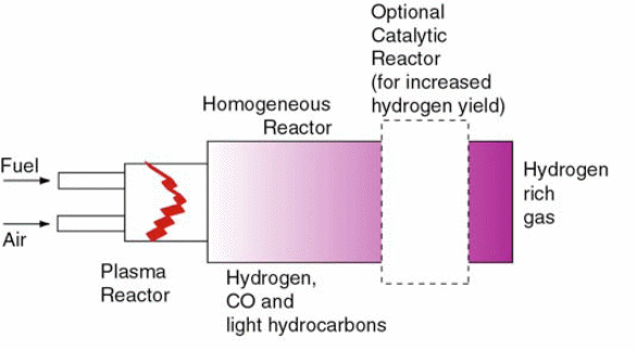
Plasmatron Technology
Plasmatron Technology is yet another innovative advancement made in the field of alternate fuel and the plasma discharge is converted to fuel here. As the Plasma Science and Fusion Center makes it clear, “Plasmatron fuel converter technology consists in the use of a plasma discharge for the initiation of reformation process. Proper placement of the CW discharge is used in a flowing air/fuel mixture that is very rich. Proper preparation of the fuel and fuel/air mixture is required for optimal operation.” (Bromberg et al 2005). The procedure of converting the plasma discharge to fuel with the help of the plasmatron fuel reformer is evident from Figure 1:
Recent Engine Trends
The future of diesel and petrol engines is centered around four research areas namely direct injection, fuel cells, hybrid engines and electric propulsion. An elaborate discussion on these recent trends will be dealt with at the end of this paper.
Research methodology
A qualitative approach is employed for the purpose of the research as it helps to achieve the aims of the research. For this, the researcher has tried to draw conclusions from the literature reviewed and every effort is made by the writer to present the research findings quite objective. The analysis of figures is made use of wherever necessary to bring in clarification to the ideas discussed. The data used in the paper is qualitative rather than being quantitative and this has made the exercise of critical analysis more significant in the work. The data analysis focuses on the development of IC engines and unearths the gradual development of both the petrol and diesel engines. It also makes a comparative and contrastive analysis of the working of both the engines.
Data Analysis
Heat engines may be classified according to where the combustion of fuel takes place, i.e. either outside the working cylinders or inside the working cylinders. If the combustion of fuel takes place outside the working cylinders the engine is called the external combustion engine (E.C. engine), and if the combustion takes place inside the working cylinders the engine is called the internal combustion engine (I.C. engine).In internal combustion engines the working fluid is the products of combustion of fuel-air mixture.The most common examples of the external combustion engines are the steam engines and steam turbines where the working fuel is steam. In these external combustion engines the combustion of fuel takes place in a boiler where steam is produced by the energy of combustion.
The steam so produced is made act on the piston of the steam engine cylinder or on the blades of the steam turbine, producing external power. Other examples of external combustion engines are the hot air engine and the closed cycle gas turbine. In all external-combustion engines the working fluid is entirely separated from the fuel-air mixture. In internal combustion engines there is direct conversion of thermal energy, obtained by combustion of fuel, to mechanical power. Since there is direct combustion of fuel inside the cylinder, in contrast to external combustion engines, these engines do not have accessories like boiler, condensers, etc. Further, due to direct combustion of fuel inside the cylinder the temperature produced is very high, say above 2000 ºc. The high temperature and the absence of heat transferring surfaces between the burning gases and the working fluid which causes heat losses, make it possible to obtain high brake thermal efficiencies, nearly 30 to 40 per cent.
Comparison of internal and external combustion engines
The advantages of internal combustion engines over external combustion engines can be summarized as follows.
- Higher overall efficiency.
- The working fluid is discarded. No facility for its cooling or conserving is necessary.
- Cooling system has to dissipate much smaller fraction of the energy of fuel.
- Lower weight to power ratio except for very large units that is units of more than 10000 kW.
- Required less space.
- Greater mechanical simplicity.
- Easy and instantaneous starting from cold conditions.
- Lower first cost except for very large units.
The advantages of external combustion engine plants are:
- Large external combustion plants are steam turbines and since they do not have any reciprocating parts so they are free from vibrations and have all other advantages of a rotary machine.
- External combustion engines can work with cheaper fuels and also on solid fuels.
- External combustion engines have higher starting torque and are self starting engines (except closed cycle gas turbine), whereas internal combustion engines are not self –starting engines.
- There is no cylinder cooling problem; in fact steam jacketing is done in steam prime movers.
- When the plant is steam turbine there is no lubrication problem. Even with the steam engine, lubrication problems are less as it generally a slow speed machine with lower temperature in the cylinder.
- Plants are less noisy.
- Large plants require less space, have better weight distribution, and have low initial cost. In large plants overall efficiency is similar to I.C. engines.
I.C. engines are very popular where space or weight considerations are important; hence these are very common used in mobile units such as scooters, motor cars, tractors, locomotives, mobile generating sets ,aero planes, ships etc. They are also used as stand-by units in large power plants. The main advantage of open-cycle gas turbine over all other internal combustion engines is its small weight and bulk for a given power output and it is therefore used in high powered aircrafts.
Classification of I.C. engines
The I.C.engines may be classified on following considerations:
- Fuel: This classification is according to the type of fuel used by the engine. Gas, petrol, and oil are the commonly used fuels. Some engines are bi-fuel engines. In these engines the main fuel is gas but in addition small quantity of liquid fuel is also injected at the end of compression stroke.
- Operating cycle: This classification is according to the thermodynamic cycle on which the engine works. The cycles commonly used are constant volume or Otto cycle (mostly petrol and gas engines), Diesel cycle (mostly low speed oil engines) and mixed or limited pressure cycle (mostly high speed oil engines).
- Ignition system: This classification is according to the method of ignition of fuel. Petrol and gas engines are the spark –ignition engines (S.I. engines).The spark may be produced by battery or magneto system.The diesel oil engines are the compression –ignition engines(C.I.engines).
- Number of strokes: This classification is according to the number of strokes required for the completion of one cycle. When the engine cycle is completed in two strokes (i.e. one revolution of crankshaft) the engine is called a two-stroke cycle engine, whereas when the cycle is completed in four strokes (i.e. two revolutions of the crankshaft) the engine is called a four-stroke cycle engine.
- Number of cylinders: This classification is according to the number of cylinders an engine has. The engine may be single –cylinder engine or multi-cylinder engine.
- Arrangement of cylinder or cylinders: This classification is according to the axis of the cylinder, which may be horizontal, vertical or inclined. If the engine has more than one cylinder, then the classification can be according to their relative arrangement. The various arrangements are in-line, V-arrangement, opposed cylinder or opposed piston arrangements, radial arrangement, etc.
- Single-acting or double acting: This classification is according to the combustion of fuel on one surface of piston or on both sides of piston. If the combustion takes place on one side of the piston, the engine is called a single-acting engine whereas in double acting engines combustion takes place on both sides of piston. I.C. engines are mostly single-acting.
- Speed: This classification is according to the speed of the engine, low, medium or high. Engines having rmp above 900 are called high speed engines and less than 400 rmp are called slow speed engines.
- Cooling system: This classification is according to the cooling of engine cylinder. I.C. engines may be air-cooled or water-cooled.
- Intake system: This classification is according to the suction of engine. The suction of charge may be natural aspiration, through supercharger or through scavengers.
- Lubrication: Engines are classified according to the engine lubrication system, i.e. a wet sump, dry sump, or pressurized lubrication.
- Piston: Engines are classified according to the shape of piston-trunk or skirt type. Also, whether the piston is cooled or uncooled.
- Valves: Engines are classified according to the type of valves used-poppet, sleeve, rotary, ports, etc.
- Starting: Engines are classified according to how an engine is started, i.e. by be compressed air, inertia, cartridge or by an electric motor.
- Governing: Engines are classified according to the method of governing- hit and miss, quality, and quantity governed engines.
- Function: This classification is according to the use the engines are put to. Engines used in pumping stations, power houses and industries are stationary engines and those used in automobiles, aero planes, locomotive are classified as mobile engines.
Engine mechanism
The engine mechanism for a four strokes, spark-ignition, and vertical internal combustion engine consists of a cylinder block in which reciprocates a piston. Piston forms a movable wall in the combustion space. To reduce friction between the piston and the cylinder and also to avoid the leakage of high pressure gases from the combustion space piston rings are provided on the piston. Power developed inside the cylinder is transferred to piston which gets reciprocating motion. The piston is connected to the connected to the connecting rod by a pin named gudgeon pin. This end of the connecting rod is known as small end of the connecting rod. The other end of the connecting rod called big end is connected to the crank arm by a pin named crank pin. For balancing, crank arm has balance weight. The crank is further fixed rigidly to the crankshaft. The reciprocating motion of the piston is converted to the rotary motion of by the connecting rod and crank mechanism. Crank-shaft which has now the rotary motion is supported in main bearings. The power output is from the shaft through pulley flywheel or brake drum attached on it.
Crankshaft also transmits power to camshaft which in turn drives all the accessories (fuel pump, oil pump, etc.) and also allows the function of valves. Camshaft may be driven either by timing gears or a chain at half the crankshaft speed. Camshaft makes the cam to rotate with its surface sliding always in contact with a plate or roller. The tappet is hinged freely to the push rod, the motion of which is transmitted to the rocker and then to the valve rod, against the valve spring pressure. The rotation of the cam makes the valve rod to move up and down and it opens and closes the valve, against the spring pressure, in the valve guide. The engine has two valves; one of these is the inlet or suction valve and the other the exhaust valve. Both the valves are provided in the combustion space above the combustion chamber.
The openings in the cylinder head for inlet and exhaust valves called ports. The pipe in the single cylinder engine or system of pipes in multi- cylinder engine which connects the inlet ports of the various cylinders to a common air intake for the engine is called the inlet manifold. Similarly, exhaust manifold embraces exhaust pipes of all the cylinders.
Cast integral with the cylinder body or separately bolted at the lower end is the crankcase which serves as an oil sump for the storage lubricating oil. An oil stick or dip stick is provided for checking the lubricating oil level. For drain off purpose a cock is provided at the bottom of the crankcase. The cylinder is shown with the water jacket for its cooling.
The combustion chamber forms the top part of the cylinder. The communication of both the inlet and exhaust passages with the cylinder space is via this chamber. In case of spark-ignition engines the charge is mixture of fuel plus air, and for its combustion spark plug is provided at the cylinder top. In the case of compression ignition engine the injector is fitted at the top of the cylinder for the supply of fuel. The ignition in the C.I. engines is due to the high compression ratio existing in the combustion space at the time of fuel injection.
In a multi-cylinder engine the cylinders, pistons, etc., are all identical and all connecting rods are fastened to a common crankshaft. The angular positions of the crank pins are such that the cylinders contribute their power strokes at different timings so that the torque is more uniform.
I.C. Engines Terminology
The following terminology is often used in I.C. engines.
- Bore: The inside diameter of the cylinder is called bore. It is a linear measurement and is given in cm or mm.
- Top dead centre (T.D.C): The extreme position of the piston at the top of the cylinder (head side) is known as top dead centre (TDC). In the case of horizontal engines this is known as the inner dead centre.
- Bottom dead centre (B.D.C): The extreme position of the piston at the bottom of the cylinder is known as bottom dead centre (B.D.C.). In case of horizontal engines this is known as the outer dead centre (O.D.C.).
At the dead centers the piston reverses the direction of its motion and its velocity therefore equals zero at these points.
- Stroke: The distance between the extreme positions of the piston, i.e. the distance between the two dead centers is called the stroke length. Stroke length is equal to double the crank radius.
Description of parts
Cylinder: In I.C. engines cylinders have to withstand very high pressures (about 70 bar) and temperatures (about 2500º C) because there is a direct combustion (explosion) inside the cylinder. In supercharged engines pressures may be even higher. Also, the cylinder has to take the side load of the piston and acts as a bearing. It contains the valve seats and ports and supports the valves and valve-actuating mechanism. Therefore the materials of I.C. engine cylinders should such that it can retain strength at elevated temperatures, should be good conductor of heat, and sufficiently resistant to rapid wear and tear due to fast moving reciprocating parts. For cylinder generally cast iron ordinary cast iron is used, but incase of heavy duty engines alloy wheels are also used. In the cases where lightness is also an important factor, as in the case of aero planes and automobiles, aluminum alloys are used. Sometimes sleeves or lines are inserted into the cylinders which can be replaced when worn out.
Since the temperatures are very high inside, cooling arrangements are necessary. The cooling may be either water or air cooling. In case of water cooling a separate jacket is cast integral with cylinder around it. In this continuous circulation of water can take place. When air cooling is adopted fins are provided around the cylinder when it is cast. This increases the area of heat transfer.
In case of multiple cylinder engines, the cylinders are normally cast in one block, known as cylinder block. For cooling purposes, water passages are provided around these cylinders. The cylinder blocks are made of cast iron. Sometimes when lightness is the consideration, as in aero planes, the cylinders are made of steel and are heat treated on the inner surface for increased wear resistance.
Piston and piston rings: The function of the piston is to transmit the gas force to the connecting rod and thence to the crank. Internal combustion engine pistons are usually made of aluminum, cast iron, and cast steel. Aluminum has advantage of higher thermal conductivity and lower specific gravity. These pistons are hollow type (the trunk type being the most common) because here only one of the face is the working face. In aircraft engines lightness and good thermal conductivity are desired and hence pistons are of aluminum alloy.
The piston is fitted with several piston rings, which are commonly made of cast-iron but sometimes of ring steel. These materials retain their elastic properties at fairly high temperatures. The upper piston rings are called the compression rings, because these when cut and sprung on be the periphery of the piston press hard against the surface of the cylinder; thus the high pressure gases in the engine cylinder are rendered incapable to leak pass the piston rings into the crankcase. These rings are first turned slightly oversize than the barrel diameter and then cut obliquely so as to form a lapped joint when compressed. The lower piston rings are the oiling rings or the oil control rings. These are made in several shapes. The oil rings have a groove with several holes so as to transfer the excess lubricating oil from the cylinder walls to the drainage holes in the piston which send it back to oil sump.
I.C. engine pistons are longer as compared to steam engine pistons. The reason for this is that in steam engines the force of piston rod and connecting rod (forces due to obliquity) are balanced by crosshead guides, but in I.C. engines due to absence of crosshead the whole load comes on piston. Hence to increase the bearing area between cylinder and piston, length of piston is increased.
But when the power developed is very high, even this arrangement fails, so in such cases I.C. engines may provided with crosshead mechanism.
Valve and valve mechanism: The valves are usually mushroom shaped (known as poppet valves) with conical seating surfaces. The face of the valve and its seat on the cylinder are very accurately ground at angle of 30º or 45º. The material for the inlet valve may be plain nickel, nickel-chrome or chrome-molybdenum, and for the exhaust valve the material may be nickel- chrome stainless steel, high nickel- chrome ( austenitic steel), and tungsten steels. These materials are good enough to withstand mechanical forces, high temperatures, and corrosive and erosive effects of the high velocity cylinder gases.
The valve mechanism gets its power and direction from the camshaft which in turn is rotated by the crankshaft. In the cycle which is completed in two revolutions of the crankshaft. Thus for the operation of valves once in two revolutions of the crankshaft the camshaft should run at half the crankshaft speed. The valves may be provided at the top of the engine or on the side of the engine cylinder. The cam lifts a camfolower mechanism, i.e. a push rod. The push rod actuates the rocker arm lever at one end. This depresses the other end of the rocker and is made up of bronze. Some clearance is provided between the rocker arm and the valve system, which can be adjusted by adjusting screw.
Correcting rod: It is usually a steel forging of circular, rectangular, I, T, or H section, and is highly polished for increased endurance strength. The small end forms a hinge and pin joint with the piston and big end embraces the crank pin. It is normally tapered along its length so as provide smaller cross sectional area towards the small end than at the big end. It has also a passage for the transfer of the lubricating oil from the big end bearing to the gudgeon pin.
Crank and crankshaft: Both the crank and crankshaft are steel forgings machined to a smooth finish. The two are held together by means of a key. The crank-shaft is supported in main bearings and has a heavy wheel, called flywheel, to even out the fluctuations of torque.
Flywheel: The turning moment of an engine varies due to (a) some strokes being idle, and (b) during power stroke itself the work produced throughout the stroke is not constant. This will result in the variation of the rate at which the work is done by the engine with a consequent variation of speed throughout the cycle. These are known as cyclic variations. In almost all cases it is essential that the speed of the engine is constant within small limits and this is accomplished by fitting a flywheel. The rate at which work is taken from the engine is constant for such intervals of time as that required for a cycle. The flywheel acts as cycle the engine develops more power and at other periods the engine develops less power or as a reservoir which gives up or absorbs energy as required. When a flywheel gives up energy its speed decreases and conversely when energy is absorbed its speed slightly increases. Both increase and decrease of speed is in some limits. The alternate taking in and giving out of the engine within the required limits from revolution to revolution; so the action of flywheel is continuous or cyclic.
The absorption of energy by flywheel is due to inertia or mass. It is made in the form of a heavy thoroughly balanced disk fitted onto the crankshaft. The heavier the flywheel more stable the uniform will be the operation of the engine. The flywheels for peripheral velocities below 50 m/s are manufactured from cast iron; for higher velocities cast- steel is used. When the diameter of flywheel exceeds about two meters split type design is used.
In multi-cylinder engines the power strokes are arranged to occur at evenly spaced intervals of crank angle, hence a smaller flywheel is required.
Events of operation in I.C Engines
For all internal combustion engines the important events taking place in side a cylinder can be summed up as follows.
- The correct amount of charge is taken up in the cylinder. In case of spark -ignition engines the charge consists of air-fuel mixture and for compression-ignition engines the charge is air only.
- The charge inside the cylinder is compressed to desires ratio. In case of spark-ignition engines value of compression ratio is from 6 to 10 and in case of compression-ignition engines value of compression ratio is from 14 to 20.
- In case of compression-ignition engines the charge does not have fuel, so fuel i.e., diesel oil, is injected at the end of compression by means of a nozzle called injector.
- In case of compression-ignition engines the ignition of charge (fuel+air) is by means of spark in the cylinder. In compression ignition engines due to higher compression ratio the pressure and temperature are higher and ignition of fuel takes place automatically as it is injected. However, if the values of pressure and temperature are not sufficient to cause self ignition (say, at the time of cold starting some external aid is required to produce ignition).
In the case of spark ignition engines the ignition of charge (fuel +air) is by means of a spark in the cylinder.
- The energy obtained from expansion of products of combustion is transferred to the crankshaft by means of piston, connecting rod and crank.
- The products of combustion are exhausted out after expansion, in order to make way for the fresh charge.
Thus the cycle is completed.
If in an engine all these operations take place in two revelation of the crank shaft i.e., four strokes, then engine is called four stroke engine and if these operations are completed in one revolution of crankshaft i.e. two strokes of the position, the engine is called two stroke engine. Thus in four stroke cycle engine there is one power stroke and three idle strokes. The power stroke supplies the necessary momentum to carry out internal and external work. In two-stroke cycle engine there is one power stroke and one idle stroke.
Four-Stroke Cycle Engines
In four stroke cycle engines all the events of the cylinder, i.e. , suction, compression, ignition, expansion and exhaust take place in two revolutions of the crankshaft i.e., four strokes of the piston. In petrol or gas engine (Otto cycle) suction consists of mixture of air and fuel and ignition takes place at the end of compression stroke by means of a spark. The combustion is instantaneous or nearly at constant volume. In diesel engines the suction consists of only air and the fuel is injected at the end of compression stroke, when ignition takes place automatically due to high pressure and temperature f compressed air. The combustion in slow speed diesel engines is nearly at constant pressure and in high speed diesel engines it is partly at constant volume and partly at constant pressure.
The individual strokes are
- Suction stroke: During the first outstroke of the piston, charge is induced into the cylinder. Due to the movement of the piston the pressure in the cylinder is reduced below the atmospheric pressure, and this pressure difference is responsible for the flow of charge. Air on its way to the cylinder passes through carburetor where it takes a metered quantity of petrol with it, thus forming the mixture. Only the inlet valve is open during this stroke. In practice the inlet valve opens slightly before the suction stroke starts and closes in the beginning of the next stroke. In suction stroke positive work is done on the piston.
- Compression stroke: this is in stroke of the piston. Both suction and exhaust valve are closed and the charge is compressed to the clearance volume. The clearance volume consists mainly of the volume of the combustion chamber. Compression ratio changes from 6 to 10, which is insufficient to ignite air fuel mixture. For the ignition of the charge, therefore, spark is times to occur at a point just before the dead centre, to take into account the time delay in actual combustion. Due to combustion the mixture ignites at nearly the dead point increasing the pressure and temperature at almost constant volume. In this stroke work has to be supplied to the piston for compression.
- Working or expansion stroke: Due to expansion of hot, high pressure gases the position moves out giving the power. Expansion of gases is not completely unto the outer dead point but before the exhaust valve opens. This is to allow maximum exhaust gases to go out. The pressure when exhaust valve opens is about 3-5 bar and about 60 percent gas is exhausted between the point of exhaust valve opening and the dead point, as the pressure inside the cylinder falls nearly to atmospheric pressure. Positive work is done on the piston during the stroke.
- Exhaust stroke: During this in stroke the piston clears the swept volume of burnt gases. The pressure during this stroke is slightly higher than atmospheric pressure. In a normal engine the exhaust gas trapped in the clearance volume can not be exhausted and at the commencement of the next cycle, the charge which is compressed in the compression stroke consists of the fresh air-fuel mixture and some exhaust gas left in from the previous cycle.
In practice the exhaust valve closes after the dead point is reached, and the inlet valve opens before the dead point and hence there is some overlap during which both valves remain open. During overlap fresh gas helps in driving out exhaust gas. This is called scavenging.
Four-Stroke cycle C. I Engine. In this cycle also there are four strokes which complete in two revolutions of engine. The essential difference between the S. I engine and the C. I engine is that in the former ignition takes place at constant volume while in the latter it is at constant pressure. In the S. I engine the ignition is by means of a spark whereas in the C I. engine it is self-ignition. A diesel engine has three valves, the air suction valve, the fuel valve and the exhaust valve.
- Suction stroke: during the first out stroke of the piston, charge of only air is drawn in the cylinder through the inlet valve. The pressure inside the cylinder is below atmospheric.
- Compression stroke: this is in stroke of the piston. All the valves are closed. The change is compressed to the clearance volume. Compression ratio changes from 12 to 22 (average 16 -18) which causes the rise in pressure and temperature of air sufficient to self-ignite the atomized fuel. The fuel is injected into the cylinder just before the end of the stroke through an injector. The fuel burns as it is injected and combustion is assumed at constant pressure. (In the case of high speed engine it is partly at constant volume).
In the hypothetical valve timing valves are assumed to open at the engine dead centers. In actual engines the valves do not open and close at dead centers but either open earlier or later.
Inlet valve opens before the inner dead center is reached. This is because it is desired that the valve should be open fully when the piston reaches the dead center. Time is required due to inertia effect and travel from close position to maximum open position.
I C engines are mostly high speed engines and so the charge does not have enough time to fill the cylinder when the piston reaches the outer dead center position. Further there is resistance to the flow of charge through the air cleaner, carburetor, pipe line, inlet valve etc.
Theoretically best time for expansion is when the piston is at the inner dead point. This gives maximum time for expansion. However due to time lag between the spark and actual ignition of the charge, spark is produced before the inner dead center is reached. For high speed engines ignition is advanced by earlier spark so that there is sufficient time for ignition when the piston reaches dead center. Care has to be taken that the ignition is not much before the piston reaches the inner dead center otherwise this will cause back explosion and loss of power. In diesel engines some time is required for the physical mixing of atomized fuel with air before the actual ignition takes place. Therefore the injection o fuel is timed to occur before the inner dead center, say about 5 to 15 earlier depending on the speed.
By earlier opening the exhaust valve the scavenging period is increased. Also earlier opening means that the exhaust pressure is higher than the atmospheric pressure which helps in scavenging process. Exhaust valve is closed after the dead center position. This ensures better scavenging. For some period there is overlapping i.e. both inlet and exhaust and valves remain open; this also helps in scavenging as the kinetic energy of fresh charge helps in forcing exhaust of burnt gases. The timing for opening and closing of the valves also depend on the speed. When the engine is faster for better scavenging the inlet valve is made to close later and the exhaust valve is made to open earlier. At high speeds, ignition time is also advanced.
Two-Stroke Cycle Engines
In a two stroke engine the cycle is completed in a two strokes of piston, (i.e. one revolution of the crankshaft) namely the compression stroke and the power stroke. The work of the inlet and exhaust stroke is done by a separate blower or pump while the engine piston is near the bottom dead center position.
In a four stroke engine the admission and exhaust from the cylinder are guided by the poppet valve provided in the cylinder head. In a two-stroke engine the mechanism is simplified by using the piston as a side valve in conjunction with inlet and exhaust ports cut in the cylinder walls.
Since a two-stroke engine develops twice the number of working cycles than the for stroke engine with the same crankshaft speed, a two stroke engine with the same number of cylinders, will develop theoretically twice the power than a four-stroke engine.
In a two-stroke engine the major problem is scavenging. The removal of exhaust gases from the cylinder is known as scavenging. If the burnt gases remain inside the cylinder they will dilute the strength of the fresh incoming charge, causing lowering the efficiency. In case of four-stroke engines the problem of scavenging is not a serious problem as the piston during the exhaust stroke pushes the burnt gases out of the cylinder. However, it poses a problem in two-stroke engines as the exhaust stroke is short. Therefore, some means should be provided for scavenging in a two-stroke engine. The various means of scavenging are discussed below.
Crankcase Scavenged Engines
In crankcase scavenged engines near the end of power stroke i.e. at about 80 percent of stroke length ports are uncovered, and the cylinder pressure drops to atmospheric pressure as the burnt gases leave the cylinder. Further descending of piston uncovers the admission or suction ports and the fresh charge already compressed in crankcase will enter the engine cylinder. Tie top of the piston is provided with a deflector and ports are made inclined at 45. Both these measures help in scavenging. Further the deflector and special shaped ports prevent the fresh charge from flowing directly to the exhaust port and being lost. During the return stroke the admission ports are first closed and then the exhaust ports.
In the upward stroke of the piston the pressure in the crack case lowers and the fresh charge is sucked in the crankcase through non-return automatic spring loaded inlet valve provided on the body of crankcase. The compression of the charge takes place during the power stroke of the piston. Thus in the crankcase scavenged engine both sides of the piston are working sides. On one side the positive energy is obtained and on the other side i.e. the crankcase side, acts as a compressor observing power. Net power of the engine is the difference of the two.
Due to friction in the inlet valve the admission and admission ports the volumetric efficiency of above type of the engine will be low. Crankcase scavenged engine are rarely used for m.e.p values more than 4 bar. The admission and exhaust ports open and close at equal angle on either side of the bottom dead center. This is because the piston in the engine also behaves as inlet and exhaust valves and open and hence port opening and closing will occur at equal angles on either side of the dead center position. The admission port may remain open for about 80 and the exhaust port may remain open for about 120 degrees.
Loop Scavenged Engines
In this engine the charge is supplied by a separate blower and usually pressure is 0.04 to 0.1 bars. Piston uncovers the exhaust ports during its downward stroke at approximately 65 degree before and inlet ports at approximately 55 before the bottom dead center position. When the inlet ports are uncovered the pressure inside is considerably low. From the inlet ports the charge enters the cylinder. The ports are shaped in such a way that the most of the charge flows to the top of the cylinder on the inlet side and back down on the exhaust side. This forms a loop and helps in scavenging of the top portion of the cylinder. In this type of engine piston deflectors are eliminated and the shape of the piston is flat. Pistons deflectors are heavy and become heated and up at higher outpoint. Also deflector’s pistons are unbalanced and cause rattle. Loop scavenging is more efficient than the crankcase scavenging.
Uniflow Scavenged Engines
In this engine the suction is through ports and the exhaust ports are poppet valve or the sleeve valve controlled. Both the ports are provided at the opposite sides of the cylinder. The fresh charge sweeps along the cylinder towards the exhaust ports and the scavenging is done. The main advantage of this type of engine is that the timing of the opening and closing of the exhaust valve can be adjusted to suit the engine speed and the scavenging air pressure.
Uniflow scavenging has been achieved in opposed piston engines where admission ports are at the top of the cylinder and are uncovered by the top piston and exhaust are at the bottom and are uncovered by the bottom piston. As the piston moves up and down during the power stroke the bottom piston first uncovers the exhaust ports and after some crank angle, when the pressure inside the cylinder is considerably reduced the top piston uncovers the inlet ports. The inlet ports are so shaped that the swirl is given to the incoming charge; this prevents the mixing of the fresh charge with the combustion products. In the combustion stroke when the pistons move inward the inlet ports are first closed and then the exhaust ports close later.
Comparison of Two Stroke and Four Stroke Cycle Engines
Merits of two stroke cycle
- A two-stroke cycle engine has many power strokes as a four –stroke cycle engine at the same engine speed. Theoretically, therefore, a two-stroke engine should develop twice the power of a four-stroke engine of the same dimensions. However, the extra power developed is only 70 to 90 percentages. Due to power absorbed in compressing the charge, reduction in the effective stroke and the lower compression due to valve ports, and in high speed engines due to short time available for exhaust of gas.
- For the same power a two-stroke cycle engine is lighter and occupies less floor area. This makes it more suitable for use in the marine engines.
- As the number of working strokes is double than in four-stroke engine turning moment is uniform and hence a lighter fly wheel is required.
- The more uniform turning moment results in lighter foundation of the engine.
- The mechanism is very simple as there are no valves. In some case mechanically operated exhaust valve may be provided.
- In the absence of valves, a simple arrangement can be used for reversing the engine.
Demerits of the two-stroke cycle
- In two-stroke engines particularly high speed ones scavenging is not complete due to short time available for exhaust and hence the fresh charge is diluted. This dilution of charge has been reduced in opposed piston two-stroke diesel engines by unidirectional scavenging.
- As inlet and exhaust ports open simultaneously some fresh charge containing fuel in the case of petrol and gas engines and compressed air in the case of diesel engine is lost. The thermal efficiency of the two-stroke engine is likely to be lower than four-stroke engines due to the above reasons and due to lower effective compression ratio.
- As the number of power strokes is double, cooling system presents difficulty.
- Combustion of lubricating oil is greater.
- As number of power strokes are twice there is more wear and tear.
- The exhaust is noisy due to short time available for exhaust.
There are more four stroke engines rather than two stroke engines in use, particularly those working on petrol, due to proved economy. Two-stroke cycle is however; very suitable for low speed diesel engines. For marine engine it is ideally suited due to low weight or power ratio and less head room, which are very important consideration in ships. Two-stroke engines are also very suitable for very small petrol engines used in motor cycles, scooter, mopeds etc.
Fuel Systems
The mode of entry of fuel into the engine cylinder for the spark ignition engines, and compressio0n ignition engine is different. In all spark ignition engines, a metered quantity of fuel is mixed with air before the entry to the engine cylinder. In all compression-ignition the metered quantity of fuel is injected in the cylinder at the end of compression stroke with the help of a fuel pump and an injector. In spark-ignition engines carburetor is used to mix the fuel with air, the details of which are given below.
Carburettor is a device for mixing the fuel, and air in the correct proportions so that the resulting vapor when compressed in the engine cylinder will ignite with the spark produced and forces the piston down, doing work on the piston. The main functions of a carburetor are
- To maintain a small reserve of petrol at a constant head.
- To vaporize the petrol by means of the engine suction and to produce homogeneous air fuel mixture.
- To supply the required quantity of air and petrol vapors at the correct mixture strength and according to the varied load requirements of the engine.
The simplest carburetor consists of a float chamber nozzle with metering orifice venture and throttle valve. The petrol enters the float chamber through a needle valve. In the float chamber a small quantity of petrol is kept at constant level the float closing the needle valve as the required level approaches when engine runs the air is sucked through the choke or venturi- tubing, by the engine suction. The venture shape reduces the pressure at the throat where the main jet of the petrol is located. Due to the negative pressure the petrol issues out of the jet in the fine spray and is vaporized. The tip of jet is placed higher by about 1.5mm than the normal level of petrol in the float chamber, in order to avoid leakage of petrol. The amount of petrol issuing from the main jet depends on the velocity of air through the choke tube. If the velocity of is less than about 7m/s petrol will not be sucked. From the choke tube the mixture of air and petrol vapor, in correct proportion, passes through the throttle valve to the engine cylinder. In motor cars the throttle valve is operated by the accelerator. The air: petrol ratio for current combustion is about 15:1.
The disadvantages of simple carburetor
- The simple carburetor does not supply a constant fuel-air ratio, but delivers a mixture that gets richer when speed rises and vice-versa. This is unsatisfactory because it is essential to supply practically the same fuel air ratio for better economy and efficiency in the normal range.
- It fails to supply a richer mixture when the engine is to start from the cold.
- It fails to supply a small and steady supply of fuel during idling and low load operation.
- The simple carburetor has no provisions for supplying extra fuel during acceleration and overload.
To overcome the above drawbacks supplementary devices are employed in modern carburetor.
- Fast running: at high speed the suction of petrol through the main jet is more due to higher vacuum created near the jet exit. To offset it a compensating jet is provided which is in communication with a tank open to atmosphere. The petrol is sucked through both main and compensating jets. As the air velocity increases the part of the fuel supply through main nozzle increases but the part of the supply through compensating nozzle remains constant. The combination of the two tends to decrease the richness of the mixture.
- A special rich mixture for starting engine from cold: this is achieved by closing the chock valve which is provided at the entrance of the carburetor. This results in almost cut off of the air supply and allows nearly full manifold vacuum to be applied to the fuel jet. The mixture may be as rich as 0’3to 0’7 kg of fuel per kg of air.
- A special small and steady supply of fuel for slow running or idling: a special small and steady supply of fuel for slow running or idling. In very low throttle operation the pressure drop of air through the venturi may be insufficient to draw the fuel from either the main jet or the compensating jet. Hence, for such condition a special jet is provided near the throttle valve to feed petrol to the engine, keeping the throttle valve nearly closed. This jet is known as idling jet. The air: fuel ratio during idling is about 12:1 to 13:1.
- A special rich mixture for acceleration and overload: for these conditions most carburetors are provided with positive displacement pump linked to the throttle valve, so that upon sudden opening of the throttle a small amount of fuel forced in to the air stream. Some carburettor provide a well or reserve of fuel which is added in to the air stream when the engine is accelerated.
No carburettor is needed if the engine uses gaseous fuel, gaseous fuel and air are simply mixed after passing them through orifices or nozzles to maintain a given air-fuel ratio. In large engines using gaseous fuel, the gas may be injected straight into the cylinder with the help of nozzles during the suction stroke.
Fuel injection in C.I. engines
In compression- ignition engines oil is injected in the engine cylinder against the compression pressure of 20-35 bar. The basic requirements of the fuel injection system are:
- Accurate metering of the fuel to be injected.
- Proper timing of the fuel injection.
- Suitable rate of fuel injection.
- Proper atomization of the fuel.
- Proper distribution of atomized fuel in combustion space.
The fuel oil may be injected by two systems
Air injection system, and Airless injection or solid injection system.
In air injection system the fuel oil is injected with compressed air. The air is compressed by an engine driven three-stage compressor and is stored in blast bottles at a pressure of about 60-80 bar. To the fuel valve fuel is supplied at air pressure by a governor-controlled fuel pump and the air is supplied from the blast bottles. The air atomizes the fuel by friction. The fuel valve is opened at correct time by a cam. The injection air may be as much as 10 per cent of the total charge of the engine cylinder.
The main advantages of air –injection system are very good atomization and distribution of fuel, less precision fuel pump, slight effect of supercharging due to compressed air supply and no choking of fuel value.
The main disadvantages of air-injection system are that it requires a multi-stage compressor which increases mechanical complexity and lowers the efficiency, more space is required, and lowers the efficiency, more space is required, and combustion efficiency is poor( as the temperature of combustion space reduces due to expansion of injected air).
Due to above disadvantages, and improvements in airless injection engines, air-injection engines are almost obsolete except for high powered engines using heavy viscous fuels.
Airless Injection or solid injection
The system derives its name from the fact that air is not used for injection of fuel. The fuel pump itself raises the pressure of the fuel very high (from 100 bars in small engines to 700 bars in very big engines to get long penetration). The oil is supplied to the engine in atomized form through a spring loaded injector. Engines working on solid injection system almost work on dual cycle.
Diesel or C.I. Engine Fuel Pump
It is the most important auxiliary unit of compression ignition engine. The fuel is injected against the compression pressure of 20-35 bars. The atomization of the fuel is secured through the through the injector, the pressures being 100 to 700 bar depending on the engine.
The most popular pumps are Bosch and C.A.V. make. The pump mainly consists of a plunger and a cylinder which is closed on top by a spring-loaded delivery valve connected with a pipe delivering fuel to the injector. The plunger is operated by a cam on the camshaft in the upper portion of the pump cylinder there are two parts which communicate with a suction space. The suction space is connected to the fuel tank by an intake pipe through the filter.
The pump is of constant stroke type. The fuel quantity delivered is controlled by a governing rack which rotates during operation in order to change the fuel delivery. The plunger has a helical groove and a vertical slot cut for accomplishment of the above.
In the starting position the plunger is at bottom of its stroke. Hence the two ports leading into the suction space are open and the cylinder is filled with fuel oil. On the upward or delivery stroke the plunger displaces the fuel back through the ports until its top edge covers them and then the remainder of the oil is forced out through the delivery valve. Before the plunger reaches the top of its stroke the helical edge uncovers the right hand port and the fuel is released back into the suction chamber. The position of the plunger stroke, at which the helical edge will uncover the port, and hence the quantity delivered, changes with the rotation of the plunger. The plunger is rotated by a rack which is connected to the governor.
Diesel Engine Fuel Injector. The function of an injector is to split up the fuel into a spray and inject it directly into the combustion chamber such that it is completely consumed, without smoke in the exhaust. The injector consists of a nozzle and to connect the fuel line to supply. A nozzle consists of two parts, the nozzle valve and the nozzle body.
There are two types of nozzle, pintle type and hole type. The pintle type nozzle is suitable for pre-combustion and for air cell engines. By variation in the size and shape of the pintle, cones of spray between 4 to 40 degrees can be provided according to requirements.
The orifice of the single hole nozzles can be obtained with any size hole from 0.1 mm diameter upwards. The multi- hole nozzle has any number of orifices unto ten. The nozzle is secured to the nozzle holder by cap nut.
The nozzle valve is held on its seating by a spindle and helical spring: the compression of the latter can be adjusted by a screw and nut so that the valve is lifted off its seat only when the required fuel injection pressure is reached, which varies from 100 bar to 700 bar, depending upon the type of engine. Fuel under pressure from injection pump is fed in through the inlet connection down to the nozzle valve seating. When the predetermined pressure is reached the valve is lifted off its seating and the fuel is injected into the combustion chamber. Any leakage of fuel at the end of the injection which may accumulate in the chamber surrounding the valve spring is led back to the pump suction chamber by the leak pipe attached to the upper connection. Producing from the top of some injectors is a tell-tail pin, which can be depressed by finger to ascertain whether the needle valve is operating. There is always some leakage of oil which is taken away through leak-off connection. In fact, this amount of oil leak lubricates the valve and body.
Ignition system of a petrol engine
In the petrol engine ignition takes place by means of an electric spark at the end of compression stroke. For a spark to arc or jump across an air gap of 1 mm, a voltage of about 3000 volts is required under normal atmospheric conditions. For a spark to jump across a similar gap in an engine cylinder having a compression ratio of 5 to 1 a voltage of about 8000 volts is necessary. Thus the ignition system has to transform the normal battery voltage of 6 to 12 volts to 800 volts (or greater depending upon the compression ratio) and in addition it has to deliver that impulse to the right cylinder at the right time. This accomplished by using an induction coil having small number of primary and large number of secondary windings. When the current is broken in the primary large voltage is induced in the secondary.
There are two systems of ignition for a petrol engine:
-
- Coil ignition system.
- Magneto-ignition system.
Coil Ignition System
It consists of the following components:
- Battery: It provides the low tension current. It is kept charged by a dynamo driven by the engine.
- Ammeter: It indicates the primary current in the circuit.
- Switch: It is used for putting on and off the primary circuit and is usually placed within the easy reach of the driver.
- Induction coil: It consists of a number or a number of soft iron rods or strips bound together by an insulating material which forms its centre. Over the centre are wound several turns of comparatively heavy enameled wire forming the primary winding. The secondary winding is wound over or under the primary winding and consists of up to 20000 turns of fine enameled wire, the ratio between secondary to primary turns being 50 to 1.
- Contact breaker: This is a mechanical device for breaking and making the primary circuit. It consists essentially of a fixed metal point against which another metal point bears. The points are of tungsten, about 3mm diameter face. The second point bears on a spring loaded pivoted arm. The moving point is forced apart against the pressure of the spring by means of a moving cam running at half the engine speed. Thus to give the necessary two sparks per revolution with a four cylinder engine the cam requires to have four faces. The gap between the two points may vary from 0.25 mm to 0.5mm.
- Condenser: A condenser is provided in parallel with the contact breaker to (a) avoid sparking at contact breaker points, and (b) to induce high voltage in the secondary circuit. The condenser functions as follows:
As soon as the primary circuit opens by the contact breaker points, current from battery starts charging the condenser which is connected in parallel. This also avoids the spark at the contact breaker points. Once the condenser is fully charged the flow of current stops and the magnetic field in the induction coil collapses. This collapsing of magnetic field further charges the condenser increasing its voltage more than that of the battery. This reverses the flow of current, i.e. the current starts flowing from condenser to battery; consequently magnetic field in the coil is also reversed. This rapid collapse and reversal of magnetic field in the coil causes very high voltage in the secondary.
- Distributor: The high voltage current is led to the correct plugs, according to firing order of the engine, by means of the distributor. A spindle passing right through the distributor body is driven by the engine at half its speed and at the top of this is a rotator or carbon brush which, as it rotates, passes over brass segments in the distributor cover. Each of these segments is connected to a sparking plug, and as the rotor passes over the segments, contact breaks and high voltage current passes through the rotor and brass segments to the corresponding spark plug. For compactness the contact breaker, the condenser, and the distributor are made in one unit. The spindle on which contact breaker cam is mounted also carries the rotor of the distributor. Modern distributors contain mechanism for automatically advancing and retarding the timing of the spark in accordance with the engine speed.
- Spark plug: The spark plug is the means of transforming the requisite voltage generated by the ignition system into a spark within the combustion chamber of the cylinder in which the piston has reached T.D.C. at the end of its compression stroke and the charge is ready for ignition. A spark plug consists of an out casing which can be screwed in the combustion chamber. Within the casing is an insulated electrode sealed to prevent leakage to the spark plug gap. A second electrode is fastened to the grounded part between them varies from 0.45 mm to 0.65mm.
Magneto Ignition System
The magneto ignition system is an alternative to coil ignition system. In this system instead of battery a magneto (generator) is used. Primary coils of a few turns and secondary coils of large number of turns are wound across the armature of the magneto or generator.
Although a considerable voltage is required to bridge the air gap inside the cylinder where the charge is under pressure, yet once a flow of current is established the voltage required for the spark may be considerably reduced. In this mechanism the flow of current is established by keeping the switch closed during the initiation of the current. Once the flow starts the opening of the switch causes the spark. The low voltage spark results in a cheap and easily insulated ignition.
The magneto trip gear, of course, imposes a definite limit on the speed of the engine and when starting a cold engine, condensation sometimes occurs on the switch causing a short circuit. This can be avoided by the simple expedient of heating the switch, prior to starting of the engine. It should be observed that since the magneto generates an alternating current, it should be so timed that the highest emf occurs when the contact points of the ignition switch are separating. This position is marked on the end of the armature shaft. Further, since the voltage is small, good electrical connections are imperative, and particular attention should be paid to the earth return through the base of the magneto.
Advantages of battery system
- At low speeds, for starting and cranking purposes, it offers better sparks.
- Adjustment of spark timing has no detrimental effect over the complete ignition timing range.
- Parts requiring maintenance are in easy approach. Periodical maintenance is small.
- The initial cost is low.
Disadvantages
- With the increasing speed, sparking voltage drops.
- Battery needs regular attention. If battery runs down it becomes difficult to start on self.
- Due to battery the system is bulky.
Advantages of magneto system
- In absence of battery and connecting cables, system is more reliable.
- The system is more reliable for medium and high speed engines.
- With the use of better metals for magnets, the system can be made quite compact.
Disadvantages
- At low speeds and for cranking purposes the voltage is low.
- Adjustment of the spark timing has detrimental effect upon the voltage.
- A powerful voltage at high speeds causes burning of the electrodes.
Comparison of Petrol and diesel Engines
The following are the salient points:
- Petrol engines work on Otto cycle and diesel engines work on Diesel or dual combustion cycle. Petrol engines are spark ignition (S.I.) engines whereas diesel engines are compression ignition (C.I.) engines. For petrol high self ignition temperature is desirable but for diesel oil low self ignition temperature is desirable.
- Compression ratio used in petrol engines ranges from 6 to 10 (average 7-8) whereas in diesel engines it ranges from 12 to 22(average 16-17). The higher ratios employed in C.I. engines result in higher thermal efficiency. The details of operating pressures are as below.
Pressure S.I. engine Diesel engine
Compression 7 to 15 30 to 50 bar
Maximum 50 to 60 bar 60 to 120 bar
bmep (max) 10 bar 20 bar
- Higher compression ratio in diesel engines results in higher pressures; therefore, diesel engines are sturdier and heavier. Diesel engines weigh about 2 to 10kW delivered, whereas petrol engines weigh about 0.5 to 3 kg per kW.
- Petrol engines can run at higher rmp, say up to 5000 rmp, compared to diesel engines, and say which run up to 3500 rmp. As petrol engines are lighter in weight.
- There is a considerable difficulty in the supply of charge of uniform mixture strength in all the cylinders of a multi-cylinder petrol engine and therefore the charge in some cylinders may not be conductive to optimum performance. In diesel engines on the other hand there is excellent distribution of fuel to the cylinders.
- In petrol engines there can be limited supercharging because of detonation, whereas in diesel engines supercharging reduces knocking. In C.I. engines the limits on supercharging is only on considerations of power required by the supercharger, and thermal and mechanical stresses.
- Since the efficiency of the diesel engines is higher than of petrol engines, heat lost in exhaust is lesser than in the case of petrol engines. This means in diesel engines the exhaust temperature is comparatively low. Excess air (especially in two- stroke engines) in diesel engines also helps in lowering the exhaust temperature.
- Starting of diesel engines is more difficult due to the greater cranking effort required to overcome the higher compression ratio. In cold weather the problem of ignition of fuel is more serious due to cold air in the combustion chamber. However, starting of diesel engines is unaffected by humidity, dew point, or condensation.
- For the same power output petrol engines occupy lesser space than the diesel engines.
- In diesel engines governing is done by varying the quantity of fuel( quality governing) whereas in petrol engines governing is done by varying the mixture, throttling quantity governing quality governing is more efficient. Since in diesel engines there is a direct control of the quantity of fuel injected and a rapid and positive means of charging this quantity, these engines produce better acceleration.
- Diesel engines can stand rougher duty because these are not only stronger but also are rated below their maximum power output because of smoke limitations. The exhaust of diesel engines has odour.
- Diesel engines have costly injection system and complicated speed governor. In petrol engines the ignition system and the carburetor may not be costly items but may create many operational difficulties.
- Diesel engines have low specific fuel consumption compared to petrol engines, both at full and part load.
Diesel engines- 0’271 kg/kWh
Petrol engine- 0’3 kg/kWh
- This also means less storage of fuel for diesel engines for equivalent work than petrol engines.
- Diesel oil being less volatile, evaporation losses are less. This reduces the fire risk compared to petrol.
- Initial cost of the petrol engines is less due to being less sturdy and is less costly fuel supply system. Particularly in the automotive field initial cost is further reduced due to large scale production.
- Maintenance cost of diesel engines is more due to skill required for repair of injection equipment. The replacement also is costly.
- The engine life for two types of automotive engines is: diesel engine -150000 km, petrol engine 60000 km.
- Two stroke petrol engines are wasteful of fuel as some of the fuel is lost while scavenging. There is no wastage of fuel in two stroke diesel engines.
- From above comparison it may be noted that petrol engines have low initial cost, low weight and smaller size for same power, requires less cranking effort for starting and have less objectionable exhaust gas odour. Because of these reasons they are mostly used where lightness in weight is preferred, i.e. in aero planes, automobiles and where the noise required is less, and working is intermittent.
Diesel engines have low specific fuel consumption at both full and part loads, less fire hazard, use inexpensive fuel, longer life, and more suited to two-stroke cycle operation. Because of these reasons they are mostly used where longer running is desired, on heavy duty equipment, heavy vehicles, stationary plants, generating sets, marine propulsion, etc.
Discussion and Conclusions
The literature review and the data analysis done in the paper convince one of the significance and the role played by both diesel and petrol engines in a technologically advanced modern world. There is no doubt that there will be a great scarcity of both petrol and future for the generations as both of them are non renewable fuel resources. As it is evident from the literature reviewed, the current research in the field of engines is to enable renewable energy for transport. The possible transport fuels like bio diesel, methanol and ethanol assume greater significance under the present conditions. The use of vegetable oils as fuels is yet another area of concern as there are successful efforts to convert fuels from castor oil, palm oil, cottonseed oil esters etc. The use of plasmatron technology for the making of fuels is another innovative foot step in this regard. The study also point out that the recent engine trends are very much focused on four areas of research namely direct injection, fuel cells, hybrid engines and electric propulsion.
Direct injection
Direct injection of fuel is a recent development and “direct injection is where fuel is injected (directly) into the cylinders, not mixed with air in the inlet manifold or inlet ports before being drawn into the cylinders.” (Engine Trends 2008).
Direct injection is successfully used in the production of cars in Japan by 2000 and Mercedes Benz and Siemens make use of the direction injection system in Australia. The direct injection system has a number of advantages over traditional diesel and petrol engines and the greatest advantage of direct injection system is that “the fuel can be placed in the combustion space in a more controlled manner than with conventional (inlet) injection systems.” (Engine Trends 2008).
Electric Propulsion
The idea of electric vehicles characterized the development of electric propulsion in the early 1900s. But the system had its own disadvantages as batteries remained “large, heavy, expensive, slow to recharge and have a limited life” (Engine Trends 2008) and therefore people thought about the concept of a fuel cell to preserve electric power.
Fuel Cells
Another major trend connected with the development of engines is the move to use fuel cells to generate electricity. It is proved that “The fuel cell, as used in space-craft, reverses this reaction combining hydrogen and oxygen to release electrical energy with pure water as a by product.” However, the efficiency of the fuel cell can be affected “because of the conversion process, carbon dioxide is a by-product (although CO2 is also produced if fossil-fuel power stations are used to generate hydrogen), and sulphur can poison the fuel cell if it get past the hydrogen generator.”
Hybrid Engines
The most modern trend towards the development of diesel and petrol engine is that of Hybrid engines: “A hybrid propulsion system uses a petrol or diesel engine with an electric motor in some combination.” (Engine Trends 2008). The hybrid cars have become the trademark for modern engines that make use of bio diesel and in the future one can expect greater innovative trends in the field of petrol and diesel engines.
The major conclusions that can be drawn from this paper are:
- The historical development of diesel and petrol engines can be traced back to the development of automobiles.
- The development of diesel and petrol engines has revolutionized the global technological scenario.
- The indiscrete use of petrol and diesel has posed many environmental issues and this has necessitated more researches in this regard.
- There is a great scarcity of diesel and petrol as they are non-renewable resources and this has increased the demand for these fuels.
- More studies and researches need to be conducted on the availability and production of renewable fuels like bio diesel, methanol and ethanol.
- Hybrid engines can best be identified as the best form of engine that suits the need of the time.
- Diesel and Petrol engines resulted in the boom on Global trade and commerce.
Recommendations for future work
The paper suggests the following recommendations:
- Further studies in the field of nano technology may result the development of smart compressed fuel, and perhaps, self sufficient, no fuel engines.
- More powerful and productive engines and fuel cells are to be designed so as to meet the requirements necessary for renewable sources of fuel.
- Measures are to be undertaken to promote the production of hybrid cars and other vehicles to ensure better efficiency and less pollution.
Bibliography
Alternative Transport fuels. Web.
ANIL (2005-2008). History of Cars. Web.
BELLIS, Mary (2008). Rudolf Diesel (1858 – 1913). Web.
BLARIGAN, Peter Van (2000). Advanced Internal Combustion Engine Research. Web.
BROMBERG, L et al (2005). Plasmatron Fuel Reformer Development and Internal Combustion Engine Vehicle Applications. Plasma Science and Fusion Center. Web.
Diesel and the Economy. West Coast Collaborative. Web.
Diesel — a Petroleum Product. (2006). Energy Information Administration. Web.
Diesel Engine: The Britannica Concise Encyclopedia: Diesel Engine. (2008). Answers Corporation. Web.
Engine Trends. (2008). 4WD Online. Web.
GOPAL R S, Chithra. Global Automobile Industry: Changing with Times. Web.
HAVERSIAN (2002). Diesel Engine. Everything2. Web.
KNOTHE, Gerhard (2001). Historical Perspectives on Vegetable Oil-Based Diesel Fuels. Vol.12. Web.
SMIL, Vaclav (2007). Journal of Global History: The Two Prime Movers of Globalization: History and Impact of Diesel Engines and Gas Turbines: Abstract. Cambridge University Press. Vol. 2. Iss.3. P.373-394. Cambridge Journal. Web.
The History and Development of Bioethanol as an Alternative Fuel. (2007). Scribd. Web.
WESTBURY, Edgar T (1968). Model Petrol Engines. Model Engine News. Web.