Abstract
The history of earthquakes is as old as the earth itself. It is a phenomenon that has occurred in different places of the earth and the results have been the deformation of the earth, destruction of buildings, and the loss of human lives. The reason for the occurrence of earthquakes is because of the seismic movements of the earth when the tectonic plates move away from each other or towards each other and in the process build large amounts of energy, which is released as seismic vibrations and heat energy. Many of the earthquakes have occurred in different area of the earth including Japan, New Zealand, Haiti, and Turkey among others places, destroying property and killing people. Because of the destructive effects of the earthquakes and the fact that those earthquakes cannot be prevented from happening, engineers and researchers have been seeking for the best solutions in terms of making structures, which resist the destructive effects of the earthquakes. Retrofitting has been recommended and new other technologies have been created to address the problems. One of the most popular and widely used is the base isolation techniques, which uses dampers to absorb the energy released on a building. Research into new and better technologies has been proposed that use materials with improved properties.
Introduction
Booth (1994, p.450) argues that seismic activities occur when the tectonic plates of the earth move against each other creating a large amount of energy, which is released into the surface of the earth in the form of volcanoes and seismic vibrations. Research into the earthquake events has shown that their occurrence is unpredictable and evenly distributed on the earth (Ekström, Nettles & Dziewoński 2012). That is because earthquakes only occur in areas, which have clear geological definitions (Day 2002). According to Day (2002, p.7), the underlying explanation can be found in the movement of the plates or can be explained using the concept of plate tectonics. The large amount of energy released when an earthquake occurs ends up causing mild to severe movements of the earth. The effects are seismic vibrations, which cause lateral shear stress on buildings and other structures in the in the path of the seismic movements (Day 2002). Research has established that it is possible to identify the lines along, which tectonic movements occur and the likelihood of an earthquake occurring in that area again (Ekström, Nettles & Dziewoński 2012).
When the earthquakes occur in different parts of the world, in most parts, the earthquakes have caused significant loss to human life. Some of the examples include the earthquakes, which occurred in Japan, Turkey, Haiti, and New Zealand, among others (Day 2002). The destruction of buildings is one of the core reasons for the loss of lives in many parts of the world during an earthquake. To address the problem of the destructive effects of buildings and to the loss of human lives, researchers have recommended for the construction of earthquake resistant buildings (Dowerick 2009). Current technology to address the problem and the fact that many buildings where the technology has been applied, serve as successful examples of the use of technology to make earthquake resistant buildings.
The base isolation technology is one example of the technologies that have shown to be promising to isolate the base of the building and protect it from the action of the forces of an earthquake (Day 2002). The base isolation technology is the most widely used approach of constructing buildings to maintain their integrity during an earthquake (Dowerick 2009). The technology uses different types of dampers, which absorb the energy transmitted during a seismic vibration and prevent it from directly being transmitted to a building when it has been released by a seismic vibration (Day 2002). Here, Engdahl, Villasenor, DeShon and Thurber (2007, p.56) argue that the dampers work on different principles and the most effective of the dampers is the viscous fluid damper. The viscous fluid damper has been shown to be a cost effective component, which requires little maintenance and functions by automatically stabilizing itself after the occurrence of seismic vibrations (Day 2002). Other dampers, which have been used and proved to work for base isolated systems, include the friction and the pendulum dampers (Day 2002). However, the pendulum and friction dampers have been shown to be expensive and sometimes lead to catastrophic failures, providing further evidence that viscous dampers are the most efficient to use. This paper will explores literature on the occurrence of earthquakes, the seismic activities and their effects on the environment (Ekström, Nettles & Dziewoński 2012).
Literature Review
Seismic Activity and its Effect on the Built Environment
A seismic activity is the motion, which occurs in the underneath of the earth as a consequence of the movement of tectonic plates against themselves. Such movements are usually connected with the development of earthquakes.
Types of Seismic Activities
Seismic activities occur as seismic waves, which are surges of energy produced because of eruptions within the ground, which leads to the abrupt breaking of rocks within the earth’s crust. Two major kinds of seismic waves exist based on the exhibited motion of the earth’s plates within the earth’s crust and include surface waves and body waves (What is seismology and what are seismic waves? 2007). Surface waves travel the length of the earth’s surface, whereas body waves progress through the middle layers of the earth. It is imperative to note that an earthquake can emit seismic energy as a body wave or a surface wave (What is seismology and what are seismic waves? 2007).
Engdahl, Villasenor, DeShon andThurber (2007, p. 45) argues that body waves, which are grouped into two, progress fast and occur at a higher frequency than surface waves. The first type of the body wave is the Primary (P) or compression wave. The Primary (P) is extremely swift and is usually the first to be detected when an earthquake occurs at a seismic station. Engdahl, Villasenor, DeShon and Thurber (2007, p.45) argue that the primary wave is able to traverse rocks as well as the fluid strata of the earth with the speed of sound in the air. A typical example of the behavioral consequences of the vibrations is illustrated in the example of the clanging of window panes after a thunder occurs. The clanging is usually because of tugging and pressing of sound impulses on the glass. The same phenomenon occurs when primary waves act on rocks. Researchers have shown that it is possible for some animals such as dogs to sense P waves when they approach, a few moments ahead of an earthquake and begin to bark uncontrollably. The effects of P waves, according to Engdahl, Villasenor, DeShon and Thurber (2007, p.45), are that they cause particles to move in the direction of the movement of the waves, which is attributed to the tugging and pressing action of the waves on solid matter(Ekström, Nettles & Dziewoński 2012). Therefore, the course of wave transmission is usually along the same direction as the movement of the P waves. Secondary wave or S wave is the second type of body wave and is slower than the P wave. S waves can only traverse solid media. The S waves shove fragments of rocks in a perpendicular direction to the line of motion (Ekström, Nettles & Dziewoński 2012).
Surface waves, on the other hand, occur at comparatively lower frequencies than body waves and can be detected using a seismogram, which is one of the most reliable instruments to detect body waves. Surface waves move at low speeds, but despite their low speed, the damage and obliteration that happens when an earthquakes occurs is significant (What is seismology and what are seismic waves? 2007). However, the magnitude of the damage reduces with an increase in the depth of the earthquake.
Surface waves are also classified into two categories, which include love waves and Rayleigh waves (What is seismology and what are seismic waves? 2007). The love waves are the fastest surface waves and shift the ground in sideways motion. Rayleigh waves, on the other hand, rotate on the ground making it to move sideways as well as in the up and down motions (Wang, Sassa & Xu 2007). The shaking experienced in the course of an earthquake is usually attributed to the effect of the Rayleigh waves (What is seismology and what are seismic waves? 2007).
The Occurrence of Earthquakes
The external layer of the earth consists of numerous sections known as plates. The plates found beneath the ocean are referred to as oceanic plates, whereas the remaining plates are known as continental plates. Earthquakes can happen along the edges of plates or along faults. A large number of earthquakes happen next to the boundary of oceanic and continental plates. Beneath the earth’s outer layer, there is a stratum known as the mantle whose activity results in the motion of the plates, which are always in motion in different directions. Typically, earthquakes mostly happen if two plates bump into each other or glide against each other. Earthquakes may also happen along faults in regions that are distant from the edges of the plates. Faults are crevices on the surface of the earth where parts of a plate progress in varying directions.
The three varieties of common faults are strike-slip faults, reverse faults and normal faults (Where do earthquakes happen? 2007). When a mass of rock (the hanging rock) slithers down past a different rock (the footwall), a normal fault is formed. In this case, the footwall moves upwards while the hanging rock moves downward resulting in the two chunks of rock moving in opposite directions. Reverse faults result when a plate shoves onto another or when compression forces, which are produced by one block press against another plate, causing it to be folded. Strike-slip rifts, on the other hand, are crevices amid two plates, which slither away from one another. The most notable example of such a fault is the San Andreas Fault in California that is responsible for the occurrence of numerous strong earthquakes.
The unexpected breakage of an underground rock next to a fault is the most common cause of earthquakes. The abrupt emission of energy produces seismic waves, which cause the land to quake. The rubbing of two plates in this process does not usually occur slickly because the two plates tend to stick together as the rocks crash into each other. The stuck rocks stop moving and press against each other causing a buildup of pressure. This pressure causes the rocks to break thereby causing an earthquake. The exact underground location where the breakage of the rock occurs is known as the focus of the seismic activity, whereas the position directly above the focus on the face of the earth is described as the epicenter of the upheaval (Why do earthquakes happen? 2007).
Blasts under the surface of the earth may also lead to the formation of seismic waves that mimic those formed in an earthquake. Activities such as the construction of tunnels cause rocks to shatter hence creating explosions. However, such explosions are usually mild and do not last long (Engdahl, Villasenor, DeShon & Thurber 2007). The caving in of underground mines also brings about seismic waves that may be felt by people living in the environs of the mine. In addition, trials involving the testing of nuclear weapons such as bombs can generate seismic waves that are similar to those produced in big earthquakes. This necessitates the enforcement of global bans on nuclear testing because the detonation of nuclear weapons always produces intense seismic waves (Day 2002).
Case Studies of Earthquakes and their Effects on Built Environment
In order to understand the effects of earthquakes on the built environment, it is important to look at previous incidences of earthquakes all over the world and their observed effects. This section takes a look at three historic earthquake events and their outcomes.
New Zealand Earthquakes
The Canterbury earthquake series that took place between 2010 and 2011 was an extremely momentous event in the history of New Zealand. A crash between the Australian and Pacific plates was the key cause of the New Zealand earthquakes (McSaveney 2012). On the morning of September 4th, 2010 at about four a.m. (local time), an earthquake of magnitude 7.1 Mw hit Darfield “40 km west of Christchurch, New Zealand on the previously unknown Greendale fault” (Earthquake Engineering Research Institute 2012, p.2). The lucky thing with the incident was that there were only two severe injuries because of the timing of the earthquake. Little damage occurred on the structures in the city, and that was attributed to the up-to-date structural code with dynamic enforcement. In addition, the intensity of trembling was an insignificant fraction of the design value. However, masonry buildings without reinforcement suffered considerable damage (Day 2002). The entire financial damage caused by the earthquake was projected at 4 billion New Zealand dollars, which was equivalent to 3 billion U.S. dollars (Earthquake Engineering Research Institute 2012).
The aftershock of the earthquake later went on to cause grave damage. For example, five months after the main shock, the city of Christchurch was greatly shaken by a 6.3 Mw aftershock at around midday (Earthquake Engineering Research Institute 2012). The exact point of the event was at the “Canterbury Region of The Waipounamu/South Island, New Zealand (epicenter located at 43°58’S, 172°68’’E)” (Black 2012, p. 2). Attributed to the timing of the event, approximately 185 people were found dead in the town whose population was approximated at 370,000 people. A sum of approximately 20 billion New Zealand dollars was lost in that event.
The immense quivering of the ground yielded peak ground acceleration that was larger than 2.2 g2. There was extensive destruction of infrastructure as well as numerous cracks on the surface of the ground. In addition, the town experienced alterations in its hydrological designs. Those changes varied from immediate co-seismic liquefaction along with the adjustments of groundwater heights in boreholes, prolonged post-seismic modifications in “spring flow, river discharge and groundwater piezometric levels, to longer term shifts in groundwater level more than one year after the Mw 7.1 earthquake” (Black 2012, p. 2). All those events increased liquefaction that resulted in numerous power outages.
The long chain of aftershocks affected the structures in the region further increasing their susceptibility to damage. In addition, the elevated magnitude of quivering increased the damage to various structures. It was estimated that about half the buildings present within the Christchurch business district required to be pulled down.
Tohoku, Japan Earthquake
In the year 2011, a great earthquake of magnitude 9.0 Mw hit the eastern coast of Japan at around 2:45 p.m. local time. An area of roughly 80,000 square kilometres was ripped apart by the earthquake causing a sideways dislodgement of about 24 meters. That earthquake, which also had a tsunami as an aftershock, was the largest and the most destructive tremor ever documented in Japan. A death toll of 15,703 people was registered with approximately 5,000 people missing. In addition, about 131,000 Japanese were left homeless, whereas extensive damage was done to steel and armoured concrete buildings that were constructed before the 1970s. However, retrofitted buildings were not adversely affected. Liquefaction caused immense harm to the built environment. It was estimated that 332,000 buildings, 2,100 roads, 56 bridges, and 26 railroads were either destroyed or damaged totalling the economic loss to “over $300 billion, making this the most expensive disaster of all time” ( Earthquake Engineering Research Institute 2012, p. 3).
Much of the damage was caused by the consequent tsunami that came after the earthquake. The extremely high heights of water that were seen in Rikuzentakata caused deaths by drowning as well as destruction of property. All concrete buildings were destroyed except two big structures that had been reinforced. Despite the establishment of safety measures to avert such a disaster, water levels as high as 38.9 metres were experienced in Aneyoshi Bay. That was because the seawells intended to halt tsunamis caused the water to flow above the walls, which could not contain the elevated water levels. The tsunami was so bad that certain bridges with girders made of steel were dismantled from the piers and were pushed considerable distances into the mainland.
One of the worst outcomes of the tsunami in Japan was the Fukushima Dai Chi nuclear power plant tragedy (Earthquake Engineering Research Institute 2012). The earthquake caused the automated safeguards of the power plant to shut. The tsunami ultimately got to the plant approximately 55 minutes following the earthquake. The power plant’s off-site ability to get power was damaged by the tsunami. However, the backing generators were able to supply power to the plant until they were also flooded by water causing them to fail. Consequently, the plant did not have any means to cool its reactors leading to explosions. A tremendous increase in temperature and pressure occurred, which caused the nuclear fuel “to melt down and eventually ‘melt through’ into the containment vessel” (Earthquake Engineering Research Institute 2012, p. 4). Consequently, radioactive isotopes such as Iodine-131, Caesium-134 and Caesium-137 leaked into the ocean, air, land, as well as into the available food reserves. It was estimated that a sum of 130 billion dollars was required to cleanse the area to make it habitable once more, and it could take decades before the afflicted region became fit for human habitation.
The wreckage obtained from Lwate, Miyagi, and Fukushima (the three troubled areas) was approximated to be 24 million tonnes. That weight did not take account of damaged cars and ships. Miyagi prefecture estimated that it could require roughly three years managing the debris, which was twenty-fold the waste it generated in a year. Other cities had little progress getting rid of their debris attributed to the environmental and health concerns involved in the process. For example, handling debris containing asbestos was a key health concern. In addition, handling debris contaminated with radioactive substances (in Fukushima) was expected to be an uphill task.
West Sumatra Earthquake
A magnitude 7.6 quake hit the Padang and Pariaman areas of West Sumatra on 30th of September in 2009 (Sengara et al. 2010). There was extensive damage to buildings with fatalities as high as 1,117 people. The Padang region was characterized by un-reinforced stone buildings made famous by the availability of rounded stones in the local rivers. Widespread liquefaction was felt alongside landslides down the sharp, snaky roads in the coastal plains. The Pariaman region that was nearer to the epicentre experienced extensive damage to buildings. Approximately 135,299 homes were severely destroyed, 65,306 homes were slightly damaged, whereas 78,591 homes underwent minor damages thereby bringing the total damaged houses to about 279,196 (Sengara et al. 2010). In addition, the quake harmed crucial infrastructure in the region such as telecommunication and transportation systems.
Methodologies and Technologies Used in the Construction in Seismic Regions
The events that transpired in the New Zealand earthquake and the event of the Northridge earthquake in 1994 act as eye-openers to engineering experts and research organizations in the U.S. (Learning from the disasters in Japan and New Zealand 2012). The fact that an earthquake with such a big magnitude can take place on a formerly unmapped fault implies that such earthquakes can happen in any seismically active region. In addition, the strong resemblance between the past and current building systems in New Zealand and the United States implies that the event of a similar earthquake in the U.S. can lead to the destruction of the built environment such as that witnessed in Christchurch (Earthquake Engineering Research Institute 2012). The New Zealand earthquake tests the concentration of existing construction codes for the protection of life. It also points out the need for paying attention to the evaluation of resistance and long-standing effect of disastrous events.
This section explores measures to ensure that buildings offer safety during earthquakes. It looks at past protective measures taking New Zealand as an example. This section also delves into present and future techniques applied in the construction process in seismic regions.
Past Techniques
Engineers believed that it was buildings and not earthquakes that were responsible for causing people’s death (McSaveney 2012). During an earthquake that happened in Wellington in the year 1848, buildings made of bricks and stones gave way leading to the death of many people. The New Zealanders learned a tough lesson from that incident. Consequently, the town was reconstructed using wood, which saw less damage in a subsequent 8.2 Mw earthquake that took place in 1855.
The extensive destruction seen from previous earthquakes had a perceived outcome on public views of the dangers presented by earthquakes. Much attention was directed on flaws in building and construction particularly mediocre construction paradigms and the unavailability of any specification for earthquake-resilient designs. A by-law was prepared in 1931, which was later included in a construction code in the year 1935 (McSaveney 2012). The code proposed patterns of plans and construction to ensure that buildings could withstand the horizontal movements caused by shaking of the ground. In addition, stone buildings were to be connected strongly so that the structure moved as a single unit.
The subsequent building codes included requirements to have the capacity for modifications in building supplies and designs. For example, the 1992 New Zealand policy delineated a building’s performance to resist the compulsion anticipated in the course of an earthquake instead of setting down explicit materials, models or construction techniques. Such a policy allowed constructors to use inventive models and building techniques in the creation of earthquake-resilient buildings. The methods were intended to safeguard buildings against structural destruction in an average earthquake. However, for a major seismic activity, the key goal was to safeguard life by making certain that the building did not crumble and that people could get away from it even though the building itself was seriously destroyed.
Most of the old buildings in Wellington were strengthened, whereas some were replaced with new ones. Such measures, however, did not raise the standards of the buildings to current levels, but were intended to prevent the collapsing of buildings and to decrease the loss of lives in case of an earthquake. The incorporation of dampers made of lead and rubber bearings in the foundations of buildings lessens the movement produced by the vibration of the ground
Present Techniques
The University of Canterbury (Christchurch) is renowned globally for its investigations on the performance of buildings. It explored the behaviour of pre-stressed and toughened concrete structures and bridges in the course of earthquakes. The methods of analysis and fabrication developed in the university have been adopted by structural design regulations in New Zealand and abroad (McSaveney 2012). In addition, books produced by the university are used as model manuscripts. Some of the notable buildings in New Zealand that have this technique are the Parliament Building and the National Museum (McSaveney 2012).
Ensuring safety during an earthquake also involves processes to ensure that lifelines such as water, drainage, electrical energy, telecommunications, and transportation networks are protected from destruction. This makes certain that essential services are reinstated as soon as possible following an earthquake. Flexible joints or ductile pipes are used in the construction of water pipes in volatile grounds to stop the pipes from bursting in the event of an earthquake. In the same way, some gas pipes are welded in a manner that precludes breakage while others are substituted by polythene.
The main sources of damage in an earthquake are short-lived horizontal forces. Therefore, the earthquake resilience of a structure relies on a blend of elastic forces, inelastic deformation and the damping capability of the attached systems. It has been established by Skinner and McVerry (1975) that normal earthquakes portray one of four key traits. Type 1 earthquakes occur spontaneously and produce one major motion in a particular path. It is important to use a mixture of elastic strength and inelastic deformations to allow structures to withstand this type of earthquake. Type 2 earthquakes last a long time and produce uneven ground movements. The three factors (elastic force, inelastic deformation and damping capability) are necessary to reduce the recurring increase of deformations, which helps buildings to stand firm against this quake. The third type of earthquake also lasts long with regular movements. It is a result of fractional reverberations of the elastic ground, which causes micro-zone outcomes. Damping plays a significant role in resisting such an earthquake. Type 4 earthquakes yield serious ground destruction as well as inertia attack. For this reason, buildings require special designs to survive such earthquakes.
Permitting a structure to bend until it reaches its elastic limit during a serious earthquake allows the realization of the economy of design (Skinner & McVerry 1975). As long as the structure hasenough capability for inelastic bending and the related hysteretic damping, successful earthquake resilience may be attained. More advanced techniques are developed to raise the capacity of inelastic bending and hysteretic damping. Metallic dampers are steel gadgets made to deform permanently as a building pulsates during an earthquake (Metallic dampers 2002). The deformation process consumes some energy from the quake thereby protecting the building from harm. Proper specification of the reinforcing steel can be used to elevate the malleability of toughened concrete. However, the concrete still undergoes progressive weakening under consecutive series of harsh inelastic deformation. Structural steel components, on the other hand, may also undergo progressive deterioration because of local crumbling. In addition, costly secondary breakage may occur from the bending of flexible construction frames beyond their elastic limits. Therefore, efforts to offer an elevated ductility factor launch great doubt in the evaluation of structural performance. Some techniques such as the inclusion of special components and the use of base isolation are suggested in increasing the resilience of buildings to earthquakes.
Use of Special Components
According to Engdahl, Villasenor, DeShon and Thurber (2007, p.67), different unique apparatus such as flexible frames behave in a similar way to the strengthening props when moderate deformations occur. These frames also act as hysteretic dampers throughout huge deformations. In Japan, for example, numerous high buildings have reinforced-concrete plates with cut walls set up over their heights (Huang 2009). A different arrangement uses a group of structural bars made of steel. Those bars are set up diagonally to converge at nearly every inter-storey deflection in short lengths (Skinner & McVerry 1975). The propping and damping roles of these tools can be optimized because the standard building overloads do not act on these components. A significant portion of the frame comprises damping and propping constituents, which stretch all through the building and provide the forces that are equal to the lateral opposing force of the frame. Base support systems provide major structures with substantial isolation from earthquake attacks. In addition, they are feasible alternatives for cheap hysteretic dampers and have the necessary damper force capability of between 5 and 50 tones and the requisite operating stroke of eight inches. Such dampers can be planned to function for numerous cycles at regulated amounts of force.
Isolation of Structures
Base isolation is a procedure used in the construction of seismic-resilient buildings based on the elastic behavior of the materials in certain points within the building. The process significantly lowers the ground movements that are spread to the building when an earthquake occurs. It is estimated that the seismic energy that hits a superstructure which is base isolated is usually reduced eightfold compared to the use of normal strengthening methods (Boardman & Wood 2004). The technique has an added advantage of maintaining buildings’ antique finishes.
It is proposed that base isolation of buildings is attained by the establishment of base buttresses with huge stretchy plasticity for horizontal movements. Such isolators may perform satisfactorily in mild earthquakes, but permit the recurring upsurge of unbearable base translations and substantial weight on the buildings in severe earthquakes. In addition, they increase the frequency and ability of a building to tolerate the rapid motion of buildings when subjected to wind storms. However, the connection of a newly developed damper, which sandwiched between the bottom and the groundwork of a flexibly-mounted, set up structure functions as a rigid support during wind storms. Consequently, the period of efficacy of these braces increases thereby “reducing the earthquake attack on structures with less than a fundamental period of less than 1.0 second” (Skinner & McVerry 1975, p. 94). It is known that base isolation significantly lessens earthquake damage on short-period buildings as well as providing an easily and precisely outlined structure.
Wind and seismic excitations on rigid structural systems have been a major problem during the construction of buildings in seismic regions in the last decade (Huang 2009). A movement magnification gadget with viscous dampers to disperse the energy is an efficient solution that mitigates this problem. Further investigations reveal that the efficacy of viscous dampers greatly relies on the arrangement of the motion amplification contrivance especially the arrangements responsible for the rigidity of the device. A toggle brace damper, which is a form of ‘scissor-jack’ device, is shown to be efficient in lessening exterior excitations in a 39-story building constructed on pliable earth in a reclaimed region (Huang 2009). The events that happened in West Sumatra have also influenced the construction of the first ever 25-story seismic building in Indonesia’s capital of Jakarta (Hussain, AlHamaydeh, & Aly 2012).
Base Isolation Components
Base isolation components are developed with a number of factors in mind. Typically, one of the factors that is important when designing and developing the components to ensure that they posses high axial stiffness. High axial stress and stiffness enables the components to resist the action of the force of gravity and other vertically applied loads. It has been demonstrated that some of the forces can be transient and other forces are sustained. It is important for the system to resist the forces without undergoing any deformation, which could corrupt the integrity of the structure. On the other hand, it is important for the components to have low horizontal stiffness to ensure that the frequency of the system is lower than the frequency of the seismic vibrations to resist the occurrence of resonance, which can be destructive to a building. On the other hand, it is important to ensure that the system has to resist the energy by appropriately dissipating the energy caused by the vibrations of the building (Jankowski, Wilde & Fujino 2000).The base isolation components are discussed below.
Elastomeric bearings
Elastomeric bearings work by using a combination of different layers of metal and rubber, which form the elastomeric component (Jankowski, Wilde & Fujino 2000). The rubber that is used varies in thickness between 8 mm and 20 mm and is made of steel shims, which are used to protect the rubber from bulging when vertical loads, which are attributed to the mass of the building and the action of gravity on the component are applied on it (Jankowski, Wilde & Fujino 2000). The elastomeric bearings are used to make elastomeric systems, which are incorporated into buildings to make it stable and to maintain its structural integrity.
Research has shown that elastomeric bearings have been applied widely to make different types of base isolated systems to enable the system to absorb the energy, which is generated by the earthquake (Jankowski, Wilde & Fujino 2000).
Spherical Sliding Base Isolation
The spherical sliding base isolation is one of the earliest forms of base isolation systems that were developed in 1909 and was found to suitable for small and medium rise buildings (Jankowski, Wilde & Fujino 2000). The sliding system was introduced to replace the elastomeric system because it was discovered that when earthquakes occurs, the elastomeric system made significant failures. Theory and practical observations on the use of the spherical sliding base isolation method shows that the degree of freedom that is made by the system when the seismic vibration occurs isenough to enable the mechanism to absorb the vibrations to a limited extend (Liu, Liu, , Chen, Li, , Xia & Cui 2011).
EERC combined system
This system was developed by combining the sliding system with the elastomeric system by subjecting the interior columns to the action of natural rubber bearings and the interior bearings to the action of sliding steel elements. Liu, Liu, Chen, Li, Xia and Cui (2011, p.76) argues that the system was designed by making the elastomeric bearings to center the system each time the system was displaced by the action of seismic vibrations. It was the sliding element that made the system to dampen the action of the vibrations caused by the earthquake and elastomeric to control the torsion that occurred because of the displacement that occurred in the building. According to Liu, Liu, Chen, Li, Xia and Cui (2011, p. 75), one of the practical areas where the system was applied was in the Mackay School isolate the buildings with a lot of success.
Resilient-Friction base isolation systems
Friction base isolation systems have been applied in areas where the movement of the building attributed to the seismic vibrations was high and could not allow the Teflon system to work well. The system is made with several layers so that each layer is able to overcome the friction, which is caused by the movement of the system by a small amount. Typically, the system works by reducing the velocity of the top and bottom layers so that the coefficient of friction between the parts is reduced significantly. Liu, Liu, Chen, Li, Xia and Cui (2011, p. 75) argues that the system was experimented on a four storey building and discovered to have a number of weaknesses, which included its inability to work well in high rise buildings).
Friction Pendulum system
The friction pendulum system was developed and tested for the purpose of ensuring that the system works and overcomes the weaknesses that were identified with other systems. The principle of operation is that of a simple pendulum. The system works by using a slider, which comes into contact with the spherical surface, which has a low coefficient of friction when the system vibrates. Another component of the system is made of stainless steel and a slider that works to absorb the energy that is generated because of the seismic vibrations. Here, the systems work by allowing the slider to move on the spherical surface when a seismic vibration occurs, which is concave shaped, causing the mass that is supported by the system to move like a simple pendulum. To ensure that the building vibrates with a simple harmonic motion, the bearings provide the flexibility for the moving components to slide to and fro. The lateral displacement is made possible by the movement of the bearings on the concave surface. The damping effect is enhanced by friction that is created between the bearings and the steel surface.
Use of fluid viscous dampers
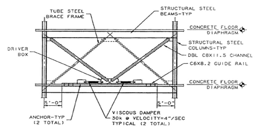
The use of dampers to absorb the energy produced by an earthquake is one of the engineering options that has been used and proved to viable in construction engineering. Engineers started using the method after the Second World War when the restructuring of the American defense industry started. Test done by civil engineers have verified the fact that the use of dampers to absorb the energy produced during the event of an earthquake can be achieved by the use of fluid dampers. The fluid damping technology can be used optimise the performance of a building in an earthquake prone or vulnerable area and protect the building from collapse and destruction. Typically, the fluid dampers are integrated into the bottom of a building to isolate the building from the ground so that when an earthquake occurs, the energy produced by the earthquake is absorbed by the dampers and the building. The underlying concepts that is used is to separate the building using the fluid dampers from the ground so that when the vibrations happen, which are caused by the seismic activity happen, they are absorbed by the dampers and the building vibrates within the limit that allows it to preserve its integrity. The underlying rationale is to enable the building to acquire the elastic properties so that when a seismic activity occurs, the deformation produced on a building is an elastic one, which enables the building to maintain its shape after the event of an earthquake. Typically, traditional structures maintain rigidly constructed buildings, which make them undergo plastic deformations, which lead to permanent destruction of a building. Conversely, when the deformation is elastic, the properties of the structure are retained because the energy caused by the seismic vibration is absorbed by deforming the elastic material as shown in the diagram below.
It has been demonstrated in research and experimental studies that when the seismic vibrations are severe the building might vibrate beyond the elastic limit and consequently get damaged completely.
Advantage of fluid dampers
Engineers dealing with earthquake vulnerable structures understand that when the fluid dampers provide greater advantages for use as a seismic energy absorption mechanism because by acting in a way that provides the system with better energy absorption capabilities when compared with other energy absorbing mechanisms. One of the advantages is that the when the energy of the earthquake has been absorbed by the fluid damper, the output of that energy is as that can easily be absorbed by other mechanisms integrated into the building (Jansen & Dyke 2000). The ultimate benefit is that the fluid damper acts in a way to reduce the effect of share stress in the building, which leads to the reduction of the internal shear stress, which causes a structure to vibrate and get deflected. In addition, the fluid damper has the advantage that it operates independently, which makes it suitable for use as a cost effective method of reducing the energy caused by seismic vibrations because no auxiliary equipment is required to operate the fluid damper (Jansen & Dyke 2000).
In addition to that, modern fluid dampers are cheaper, smaller, and easily portable and operate within the fluid pressure level, which makes them preferable than other types of mechanical dampers. On the other hand, it has been demonstrated through research and technical evaluations that fluid dampers are easy to install, work with, and procure, which makes their application to be wide and the overall cost of the building to be low. In addition to that, fluid dampers are easy to service and maintain in environments, which have undergone severe seismic vibrations. It has been demonstrated in research that fluid dampers have proved to be effective even when they are installed in military and other severe environments, which has made them popular and widely accepted for to protect buildings (Jansen & Dyke 2000).
Operation of dampers
Fluid dampers are popular for use in the construction industry to separate buildings at the base from the ground so that any seismic vibrations that are caused by an earthquake can be resisted by absorbing the energy of the vibrations. To achieve fluid damper operates in a manner such that when energy has been supplied into the damper because of the seismic vibration causes pressure deference across the piston (Jansen & Dyke 2000). The pressure difference occurs because of the action of the inertia of the fluid, which is used to absorb the energy of the vibrations. A typical fluid damper is shown on the diagram below.
The action of the fluid damper is as flows. The fluid flows between the chambers because of the action of the forces, which are caused by the vibrations. Here, when there is an action on the position, the fluid flows from chamber 2 to chamber 1 and the damping effects is attributed to the pressure difference that occurs between the two chambers (Zekioglu, Darama & Karahasanoglu 2010). It has been demonstrated in laboratory experiments that when the piston moves, the displacement of the fluid, which causes the damper to reduce the energy that is acting on the damper is equivalent to the product of the surface area of the piston and its displacement from its resting position. When the fluid volume is reduced because of the compression that is caused by the movement of the piston, the fluid develops a restoring force that gradually enables the damper to return to its original resting point. However, the action of the resisting force, which is caused by the compression of the fluid is can be retarded by the use of the accumulator. It is however, important for the frequency at, which the system vibrates to ensure that system remains secure. It is important to ensure that the system has to be designed to reach a cut off frequency of 2,000 Hz because it is a desirable property for a damper that makes a building secure from earthquakes. It is possible, when the system is being evaluated to realise that it provides additional viscous damping capabilities. It has also been established that it is possible for the damper to provide additional damping capabilities because of the development of stiffness and additional damping capabilities. It has been established that dampers have proved to be useful in the securing buildings and protecting them from the destructive effects of the seismic activities and vibrations on buildings.
Masonry construction
Masonry construction has been in use for many years in the building industry. The use of masonry work to make buildings has been shown to be challenging because of the destructive effects earthquakes have on masonry work. The underpinning reasons, which are the main causes of failure of masonry work are because the masonry work does not have integral actions on the structure where they are applied and shows inherent failure of the masonry work to provide ductile connections between the walls of the buildings (Wang, Sassa & Xu 2007). In addition, the elements which make the foundations, and the elements which make the roofs have additional problems with masonry materials. In most cases, when an earthquake happens, out of plane forces act on the walls of the building. It has been shown that the masonry structures are not able to resist the forces and that contributes to the destructive effects of the earthquakes (Wang, Sassa & Xu 2007). It has been demonstrated that the mortar that is used to make the masonry structures lacks the ductile, tensile, and shear strengths to resist the forces that are applied on the walls of a structure during an earthquake. Another weakness that makes the masonry structures vulnerable to the action of the destructive forces of the earthquake are the in-plane stiffness of the walls, which is high and ability of the masonry units to deform because of the effects of the forces. Test conducted to assess the properties of the masonry structures have shown that the masonry structures have a heavy mass and are vulnerable to the destructive effects of the vibrations, which can bend or break the masonry units at the action of shear forces.
Measures on masonry work
It has been suggested that because high rise buildings are assays in continuous use, the effects of the action of the forces that act on the masonry units and the ultimate effects of the earthquakes require the use of measures to ensure that the buildings remain safe (Wang, Sassa & Xu 2007). The approach that has been tested and proved to be useful is the use of the earthquake resistant measures, which are designed into a building to enhance the performance of the building and increase the ductility and resistance of the masonry to earthquake forces. In addition to that, different countries have developed their own standards and recommendations on the type of materials and the material properties to use to develop earthquake resistant buildings. ‘
Different international standards provide recommendations of the properties of the standard materials to use to make earthquake resistant materials (Wang, Sassa & Xu 2007). The standard recommendations are based on the concepts of the need for integral action by the masonry structures’ and the walls of the buildings, the provision of connections between the walls and the structural elements, which are used to construct the walls of the building (Jansen & Dyke 2000). In addition, there is need to ensure that the masonry unit has enough ductility to absorb the shear stress and other forces which tend to deform the structure. The roof elements and the foundation have been shown to be vulnerable to the action of the forces of the earthquake and the need for them to be reinforced with ductile materials cannot be underestimated (Wang, Sassa & Xu 2007). To achieve the strength required to resist the action of the forces of the earthquake on the building, there is need to ensure that the reinforcements are capable of resisting the out of plan and in plane forces to resist bending, stretching, and the action of shear forces. It is important to use steel, timber and reinforced concrete to reinforce the weaker sections of buildings to ensure that the structures have the structural strength required to make the building robust and earthquake resistant (Wang, Sassa & Xu 2007).
Strengthening features for seismic constructions
It has been established that the seismic activities cause the materials that are used to make buildings to crack, break, and yield to the action of the forces that are generated by the action of the seismic vibrations (Wang, Sassa & Xu 2007). Research shows that it is important to understand the seismic strengthening features so that the materials that are used opt create the structures are made to resist the action of the forces. One of the suggestions is to ensure that horizontal bond beams are integrated into a structure. The horizontal bands are applied at the points, which are critical to the buildings and which experience the highest number of vibrations when an event of a seismic vibration occurs. In addition to that, there is need to apply vertical reinforcements to resist the action of the gravitational mass of the building. Recommendations show that the application of the reinforcements should be at the corners of the building and other critical points within the structure. It has been demonstrated through experiments that the bands are able to resist horizontal forces, which are induced on the building and they can transfer the forces to the vertical walls to provide additional damping effects (Wang, Sassa & Xu 2007). The purposes of the reinforcements are to improve the integral capabilities of the structure and to preserve the integrity of the building. It has been established that horizontal reinforcement can work with vertical reinforcements to improve the structural strength of the building by enhancing the energy dissipating capabilities, the ductility of the structure, and the tensile strength of the masonry structure. It is important to note that the level of the masonry strength varies with the type of structure, where it is applied, and the level of seismic activities in that area (Wang, Sassa & Xu 2007).
Strengthening elements
Some of the recommended strengthening elements that are used to make the structure earthquake resistant include the use of plinth band, which provides the building with the ability to achieve differential settlements on soft and uneven soils. In addition, the gable band can be used to provide the building with the ability to resist the action of the out of plane forces (Utsu 2002). The gable is always placed as a continuous element with the roof band. Another element that is used here is the sill band which makes the masonry work to resist the effects of lateral and shear forces on the building. It has been demonstrated that the use of lintel bands enable the roof to maintain its integrity and prevent it from collapsing. The lintel band is applied on across the walls to partition them and provide the walls with the ability to resists the action of out of plan bending forces. Another material that has been recommended for use to reinforce masonry structures is the vertical steel. Vertical steel is usually inserted at the vertical junctions of a structure, at the corners of a building, at the windows and doors and around the jambs (Utsu 2002). The purpose is to ensure that the integrity of the building is maintained when an earthquake happens. The measurements that have been recommended for the vertical steel include the 10 mm and 12 mm of bamboo and should be inserted in a structure measuring 600 mm high (Utsu 2002).
Retrofitting
Retrofitting masonry structures has been in use for many years because most of the buildings in the world are made of masonry work (Taylor & Duflot 2005). However, it has been discovered because of intense seismic activities where masonry structures are erected, intense damage and destruction has been the results. India is on of the typical examples where masonry work has shown significant damage after an earthquake has occurred (Taylor & Duflot 2005). To address the problem it has been suggested engineering circles that retrofitting the masonry work make the structures safe for use. It has been shown that when masonry work is improperly done, the accumulated results of damages have become even worse. However it is important at this point to remember that they are reinforced and unreinforced masonry buildings and the method of retrofitting them varies from one to the other (Taylor & Duflot 2005).
Typically, when the masonry building has not been reinforced, it has been shown to suffer the greatest damage and when it is reinforced, the level of damage is small. Some of the examples of the buildings that have collapsed because they were not reinforced include the Acorn building. The building collapsed because the roof was not properly fixed to the wall, the seismic vibrations, which caused the movement of the vibrations from the east to the west, which caused the roof to slide and damage the cars which were parked below the building. The underlying reason was that the roof was not retrofitted, which is principally accepted and recommend in construction engineering.
Techniques for retrofitting
Different suggestions have been made on the retrofitting techniques that can be used to reinforce the strength of the building to ensure that in the event of an earthquake, the system maintains its integrity. One of the techniques that are used is known as shotcrete (Taylor & Duflot 2005). The technique is suitable for areas that have not been reinforced and in areas where the masonry work is weak to resist the action of seismic vibrations. In addition, the technique is most suitable for use in areas that have little reinforcements, which use solid piers to absorb the energy that is generated from seismic movements (Taylor & Duflot 2005). To ensure the system is reinforced, it is important to apply shotcrete from the inside and outside of walls to make the structure to develop the structural integrity of the building. In addition to that, shotcrete is applied when wet and allowed to set so that it develops the required strength to overcome the effects of the seismic forces. Shotcrete is made from concrete and it has been demonstrated that when it is applied in dry condition and in restricted areas, it performs better. It is also necessary to use trained and well skilled personnel to work on the shotcrete to make it suitable for use in reinforcing masonry work (Taylor & Duflot 2005).
RC and Steel Frame
Another method that is used to make the reinforcement of the masonry work do better is the use of RC and steel frames. RC and steel frames provide the masonry work with the ability to resist the in-plane weaknesses that are inherent in masonry work. It has been established that walls have a severe weakness when earthquakes happen because of the openings that exist as windows and doors (Taylor & Duflot 2005). To ensure that the structure has gained the required strength, the RC and Steel Frames are positioned in a way to enable them resist the entire force that acts on the building as lateral vibrations o the building. It is also important to apply jamb reinforcements to ensure that the structure remains firm as resistant to the effects of the earthquake (Jansen & Dyke 2000). Typically, reinforcements can be added to masonry walls from the side or by inserting them through the applications of vertical slots on the body of the structure to be reinforced. In addition to that, it is possible to insert the reinforcement from the center of the wall and apply them vertically through the core of the structure. It is important to make the reinforcement to be vertical and continuous form the top to the bottom of the structure (Taylor & Duflot 2005).
It is important to ensure that the connection between the walls has to be made by stitching the walls to give them the required additional strength. It has been shown that of wall corners are stitched correctly, the action of the seismic forces at the intersections cannot create significant damage on the structure. On the other hand, the connection between the walls and the floors should be such that the connection appropriately applied to make the system behave like a monolithic structure. When the connections are made appropriately, they provide the building with the ability to resist the vertical forces, which occur because of the action of gravity on the structure.
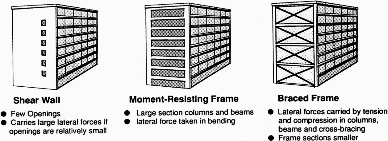
Shear walls
Shear walls are constructed vertically to ensure that they provide the structure with the required resistance to the action of vertical transverse forces, which are caused by seismic vibrations. Shear walls can be made of wood, steel, and concrete. Research has established that shear walls have serious weaknesses, which include the large amount of space taken by the walls, the weak resistance they offer weak to the action of lateral forces, and the demand they place on the structure to meet the standard requirements (Stefánsson, Guðmundsson & Halldórsson 2003). The use of different members to provide the required structural integrity makes the system to increase the number of members, which are used to reinforce the structure. The approach makes many of the construction members redundant and increases the ultimate weight of the structure and the overall mass of the building.
To ensure that a structure complies with the requirements for building codes, it is necessary to use shear wall reinforcements for 20 storeys buildings only.
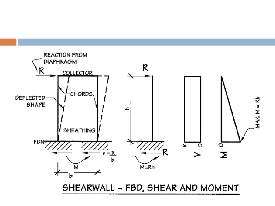
Shear walls are designed with certain considerations in mind and include the thickness of the sheeting, strut design, deflection issues, the proportions of the shear panels, anchorage requirements, and the action of the chords. Here, the thickness of the shear wall is determined by the resistance to fires and the application of lateral forces, and the need to use nails which are light (Stefánsson, Guðmundsson & Halldórsson 2003). It is important to consider issues such as height to weight ratio to create the right proportion of shear materials. The diagram below shows the action of the forces on the shear walls and shear moments on the walls.
Code provisions
It is important when the when developing earthquake resistant structures to ensure that the structure are compliant with the codes for seismically isolated structures. Different countries have developed their own codes, which included the United States, Japan, New Zealand, Turkey and many other countries, which are in seismically active regions of the earth. Some of the codes, which govern the construction of buildings, are the Uniform Building Code published in 1997 by the officials of the International Conference of Building Officials (Sahasrabudhe & Nagarajaiah 2005). The code is designed to provide guidelines for the construction of new buildings in seismically active areas. Another code is the National Earthquake Reduction Program (NEHRP), which provides that buildings, which have already been set up can be rehabilitated to using the guidelines for the Seismic Rehabilitation of Buildings (FEMA-273) to ensure that structures are made sufficiently effective to withstand the effects of an earthquakes. The codes generally specify that an earthquake resistant building should be defined by adequate stiffness to resist the lateral loads, which are caused by the vibrations of the building, lateral strengths to resist the application of lateral forces which can cause a building to collapse, the good ductility to ensure that the building is able to undergo large deformations without significant damage being caused, and the good structural configurations to ensure that the flow of inertia forces to the ground is smooth (Sahasrabudhe & Nagarajaiah 2005).
Making secure building foundations
The foundation upon, which a building is erected, contributes significantly to the resistance such as system has to the action of seismic vibrations. One of the factors to consider is the ground motions, which are caused by secondary and primary sources of earthquakes (Sahasrabudhe & Nagarajaiah 2005). In addition, the other factors to consider include the soil foundation system requirements, which entail that the soil upon which the foundation is established should haveenough compactness and strength to support the vertical loads and ensure the horizontally applied lateral forces, which are caused by seismic vibrations are resisted to ensure that the integrity of the building is maintained. In addition, it is critical to ensure that the foundation should be established to ensure that the static and dynamic forces, which are caused by the action of the seismic movements of the earth, should not induce excessive movements of the buildings, which could result in the destruction of the building (Sahasrabudhe & Nagarajaiah 2005).
It is also important to ensure that the properties of the soil are assessed and evaluated to determine the changes to the strength and other additional properties of the soil are maintained when a seismic activity occurs. It has been established that a superstructure should be erected withenough ductile strength to make it resistant to other natural forces such as the action of the wind before they are made to resist the action of earthquakes (Sahasrabudhe & Nagarajaiah 2005).
Foundation capacity design
Technical research in the area of foundations shows that the foundation should be designed to remain elastic even in the event of the worst seismic vibrations. Different codes such as the Euro codes provide the requirements to be adhered to and it is has been proposed that the soil has to be designed in prevent it for yielding or to enhance its resistance to the effects of the earthquakes (Sahasrabudhe & Nagarajaiah 2005). It is important to establish the upper and lower bounds of the soils, depending on the quality and type of the soils being used. Soils are classified into soft soils, strong rocks, deep or soft soils, rock, and shallow rocks or soils. Typically, the safety factors to consider when designing a foundation are listed below.
- Load factors-The foundation has to be designed to remain elastic and that depends on the frequency of the applied loads.
- Material safety factors-The soils design parameters should be equivalent to those of static structures.
Pad and strip foundations
Different types of foundations have been suggested to provide additional strengths to the structure that is designed to resist the action of the forces. The failure modes that can happen in such foundations should be studied to determine the best design strategy for an earthquake resistant building. Those failure modes include:
- Sliding failure-Usually occurs at the boundary of the soil and the shallow footing of the soil.
- Rotational failure-This is where the bearing capacity failure occurs when the foundation of the building rotates before the bearing capacity failure is reached.
To ensure that the foundation is appropriately reinforced, different codes recommend the use of additional confinements, which are made of steel spirals or hoops to make the piles, to provide additional resistance and include the use of raking piles (Sahasrabudhe & Nagarajaiah 2005).
Future Designs
The rationale of making earthquake structures that can resist the occurrence of an earthquake is to preserve the lives of the inhabitant when the earthquake occurs and allow them to exit safely when the seismic activity is over. With the current research and development, engineers and scientists have concluded that it is possible to construct earthquake resistant structures, which cannot be damaged by even the most severe seismic vibrations. Significant difficulties crop up when trying to design buildings with huge ductility requirements. Such problems include the relations between the regular construction burdens and seismic overloads. These burdens hasten the pace of wear and tear in the strictly plastic areas. Therefore, future designs should focus on ways of designing buildings with vast ductility requirements.
It is also known that base isolation is one of the most reliable techniques of creating earthquake-resilient buildings. However, it is impossible to reap maximum benefits from this technique if little is known on earthquake prone areas. For example, the usage of seismic isolation alongside other seismic protective systems is extremely uncommon in Indonesia despite the country’s location in a seismically active region (Hussain, AlHamaydeh, & Aly 2012). It is speculated that this is because of lack of general knowledge about the benefits of seismic protective systems and the absence of design criteria and procedures in building codes that have been in use in the past few decades (Hussain, AlHamaydeh, & Aly 2012). It is, therefore, important that such protective systems are publicized globally to maximize their use. Additionally, engineering experts require proper education and training on the procedures to improve the efficiency of the buildings (Merovich 2009).
Another suggestion put forward is to construct a building that undergoes deformation to an extreme extent and return to its original shape and size without getting permanently deformed when an earthquake occurs (Parsons, Toda, Stein, Barka & Dieterich 2000). To address the issue, a team of engineers suggested the use of the rocking frame technology, which has been proved to be effective in creating earthquake resistant structures. The technology draws on the strength of the properties of steel cables, which are used to design; steel fuses, and steel frames, which are used to reinforce a structure. Parsons, Toda, Stein, Barka & Dieterich (2000, p. 98) argues that the frame is designed to remain intact when a seismic activity occurs, irrespective of the magnitude of the seismic vibrations. To ensure that the system works as required, engineers have suggested that over 100 concentric plastic rings can be laid on the base of the foundation of the building so that when seismic waves act on the rings, the rings get compressed and end up zipping together. Parsons, Toda, Stein, Barka and Dieterich (2000, p.90) show that results the rings acting to retain the integrity of the structure because of the movement of the rings and when the earthquake is over, the rings return to their original shape and size.
Earthquake Resistant Materials
Different suggestions and recommendations for earthquake resistant materials have been made. One of the materials that have been suggested for use is timber. Timber in light in weight, is easily available, and can be easily worked on. However, the disadvantage with timber is that it cannot resist large forces and can easily break or deform when it reaches its yielding point. The solution is to reinforce the timber with steel sheets, to reinforce the timber and enable the material to develop additional strengths. When steel has been used to reinforce the timber, the steel should always take the form of timber as it bends or as it goes through deformations.
Another material that has been suggested, which has been in use for many centuries to make concrete reinforcements is concrete. Existsing standard codes, which provide the guidelines on how to prepare concrete in different settings, have been developed. According to Parsons, Toda, Stein, Barka and Dieterich (2000, p. 45), the concrete has to resist the action of the forces on the slab columns, which act vertically downwards on the columns. Steel has been widely used to make different structures and one of them is to make concrete reinforcements. The properties of the materials should include orthotropic characteristics, high ductility, homogeneity, high strength to weigh ratio.
Conclusion and Recommendations
It has been established that earthquakes are a natural phenomenon, which cannot be prevented from occurring. When an earthquake occurs, it releases large amounts of energy as seismic vibrations and heat, which are the main causes of the destruction on infrastructure and loss of human lives. Earthquakes are caused by the movement of the earth’s tectonic plates away or towards each other and occur in seismically active areas, which include countries such as Japan Haiti, and Turkey among others. The destructive effects of the earthquakes has made scientists and engineers to take many years of research and development in technologies, which could enable buildings to maintain their integrity when the earthquakes occur. One of the most widely used technologies is the base isolation technology, which works on the principle that the base of a building can be separated at the point where it makes an interface with the ground using dampers. The dampers are the ones which absorb the energy caused by a seismic vibration so that after the seismic vibration is over, the building remain intact. In addition, old buildings can be retrofitted with different retrofitting materials to increase the resistance of a building to the action of seismic vibrations. Different dampers have been developed to enable absorb the energy caused by an earthquake and include friction dampers, pendulum dampers, and viscous fluid dampers. The viscous fluid dampers have been shown to be effective when used in base isolated structures and are widely used in the construction industry. Further research has been recommended based on the best ways to isolate and retrofit old buildings and the best techniques to isolate new buildings.
References
Advanced earthquake resistant design techniques n.d. Web.
Axinti, G & Scheaua, F2010, ‘Dynamic Hydraulic Dampers for Earthquake Isolated Structural Systems’, Research Centre for Mechanics of the Machines and Technological Equipments, vol. 2, no.3, pp. 145.
Abercrombie, R E, Antolik, M & Ekström, G 2003, ‘The June 2000 Mw 7.9 earthquakes south of Sumatra: Deformation in the India–Australia Plate’, Journal of Geophysical Research: Solid Earth, vol. 4, no. 18, pp. 108.
Black, A 2012, A review of the environmental impacts from the Ōtautahi/Canterbury earthquakes. Web.
Boardman, P. & Wood, B 2004, Base-isolating New Zealand Parliament buildings. Web.
Booth, E 1994, Concrete structures in Earthquake Regions: Design and Analysis, Longman Scientific and Technical, London
Day, RW 2002, Geotechnical Earthquake Engineering Handbook, McGraw-Hill, New York.
Dowerick, D 2009, Earthquake Resistant Design and Risk Reduction, Wiley and Sons, New York
Earthquake Engineering Research Institute 2012, The 2010 Canterbury and the 2011 Christchurch New Zealand earthquakes and the 2011 Tohoku Japan earthquake: emerging research needs and opportunities. Web.
Ekström, G, Nettles, M & Dziewoński, A M 2012, ‘The global CMT project 2004–2010: centroid-moment tensors for 13,017 earthquakes’, Physics of the Earth and Planetary Interiors, vol. 4, no. 4, pp. 59
Engdahl, ER, Villasenor, A., DeShon, H R & Thurber, CH 2007, ‘ Teleseismic relocation and assessment of seismicity (1918–2005) in the region of the 2004 Mw 9.0 Sumatra–Andaman and 2005 Mw 8.6 Nias Island great earthquakes’ Bulletin of the Seismological Society of America, vol. 5, no. 56, pp. 97.
Huang, H. C 2009 “Efficiency of the motion amplification device with viscous dampers and its applications in high-rise buildings,” Earthquake Engineering and Engineering Vibration, vol.8 no.4, pp. 521-536.
Hussain, S. M., AlHamaydeh, M. H., & Aly, N. E 2012, Jakarta’s first seismic-isolated building: a 25 story tower. Web.
Jansen, LM & Dyke, SJ 2000, Semiactive control strategies for MR dampers: comparative study. Journal of Engineering Mechanics, vol.8, no. pp. 795-803.
Learning from the disasters in Japan and New Zealand 2012. Web.
Jankowski, R, Wilde, K & Fujino, Y 2000, ‘Reduction of pounding effects in elevated bridges during earthquakes’, Earthquake engineering & structural dynamics, vol. 2, no. 29, pp. 195-212.
Liu, CY, Liu, JY, Chen, WS, Li, JZ, Xia, YQ & Cui, XY 2011, ‘An integrated study of anomalies observed before four major earthquakes: 2004 Sumatra M9. 3, 2006
Parsons, T, Toda, S, Stein, RS, Barka, A.& Dieterich, J H 2000, ‘Heightened odds of large earthquakes near Istanbul: An interaction-based probability calculation’ Science, vol. 2, no. 288, pp. 661-665.
Pingtung M7. 0, 2007 Chuetsu Oki M6. 8, and 2008 Wenchuan M8. 0. Journal of Asian Earth Sciences, vol. 4, no. 41pp. 401-409.
McSaveney, E 2012, Building for earthquake resistance. Web.
Merovich, A. T 2009, “Concept paper on utilizing the FEMA P695 (ATC-63) ground motion spectral shape guidelines to adjust the target displacement in the ASCE/SEI 49 nonlinear static procedures,” in Barry J. Goodno (ed), Improving the seismic performance of existing buildings and other structures, ASCE Publications, Reston, VA, pp.443-464.
Metallic dampers 2002. Web.
Sahasrabudhe, S & Nagarajaiah, S 2005, ‘Experimental Study of Sliding Base-Isolated Buildings with Magnetorheological Dampers in Near-Fault Earthquakes’, Journal of Structural Engineerin, vol. 3, no.5, pp. 1025-1033.
Sengara, I W, Suarjana, M, Beetham, D, Corby, N, Edwards, M, Griffith, M, Wehner, M & Weller, R 2010, The 30th September 2009 West Sumatra earthquake: Padang region damage survey. Web.
Skinner, R. I. & McVerry, G. H 1975, “Base isolation for increased earthquake resistance of buildings,” Bulletin of the New Zealand Society for Earthquake Engineering, vol.8 no. 2, pp. 93-100.
Stefánsson, R, Guðmundsson, GB & Halldórsson, P 2003, ‘The south Iceland earthquakes 2000’, A challenge for earthquake prediction research’ vol. 2, no. 3, pp. 7
Taylor, D & Duflot, P 2005, Fluid Viscous Dampers used for Seismic Energy Dissipation in Structures’ Taylor Devices Inc. Longman Scientific and Technical, London.
Utsu, T 2002, ‘42 A list of deadly earthquakes in the world: 1500–2000’, International Geophysics, vol. 2, no. 81, pp. 691
Wang, H B, Sassa, K & Xu, W Y 2007, ‘Analysis of a spatial distribution of landslides triggered by the 2004 Chuetsu earthquakes of Niigata Prefecture, Japan’, Natural Hazards, vol. 1, no. 41, pp. 43-60.
What is seismology and what are seismic waves? 2007. Web.
Where do earthquakes happen? 2007. Web.
Why do earthquakes happen? 2007. Web.
Zekioglu, A, Darama, H & Karahasanoglu, S 2010, ‘Seismic Sophistication’, Civil Engineering Magazine, vol. 2, no. 4, pp. 64-69.