Abstract
Geosynthetic reinforcements on foundations and other soft soil masses is a cost-effective engineering method that substitutes conventional methods which are prohibitively expensive for embankment constructions. Geosynthetics improve engineering materials confining properties of soft soils to withstand pressures due to the earth. Different forces with varying magnitude and effects on embankments are experienced in the process. To design and construct a safe embankment, a factor of safety is determined for the material. The factor of safety is defined in the relation, Factor Of Safety (FOS) = (Resisting moment/Driving moment) =Μr/Μd.
That is also about a rigid base that underlies the clay forming the base of the reinforcement below a depth of 15 meters of clay. The failure of an embankment can be numerically modeled in the mathematical relation by B ¼ 18 m, n ¼ 2 when calculating the equilibrium of failure. Equilibrium calculations of the geometry of failure have a direct relationship with the depth of the reinforced embankment and the type of fill materials applied in the reinforcing structure.
These categories include hydraulic fills, industrial and several domestic wastes, slag, and several other fill materials. Soft soils and clean sand among other construction materials are used in the filling process and provide modifications of the properties of embarked soil in soft grounds. This paper analytically discusses the effects of reinforcements on soft soils, the factor of safety for geosynthetic designs, embankment failure mechanisms, allowable design values for geosynthetic reinforcements, and effects of reinforcements on stability. The underdrain shear strength of soft soil foundations shows a linear relationship with increases in depth. Soil improvements during excavations, geosynthetics for soil improvement, and geotechnical engineering procedures are exemplified later in detail.
Introduction
Conventional Methods for constructing soil embankments have over time become prohibitively expensive and environmentally friendly and cost-effective methods provide the most feasible alternatives. A critical analysis of these methods has led construction engineers to overwhelmingly tag the new geosynthetic reinforcement approach as a feasible and environmentally friendly approach in the construction engineering industry especially when setting up foundations on soft soils.
Various design approaches, mechanical properties of the geosynthetic materials are analytically discussed in the paper to reinforce the idea that geosynthetics are the most economically feasible solutions. One of the methods of reinforcing these embankments is the mechanism of placing a layer over the soft soil to mobilize tensile forces and mechanically confine and increase the soil’s tensile strength reducing lateral distortions and shear stress levels.
The magnitude of the impact of the reinforcement bears a close relationship with the embankment geometry, embankment safety, and the level of stiffness of the embankment. It is worth noting that, several factors may influence the failure of a geosynthetically reinforced embankment and mechanisms and design factors, on the other hand, help to mobilize the mechanical properties of these materials to make them fit for the purposed of constructions. One cause of embankment failure is the rapidity with which the construction is done. Rapid constructions cause the structure to attain its ultimate performance values giving in to applied loads, hence collapsing the whole structure. However, the benefits gained from the use of geosynthetic reinforcements outweigh the costs and the negative side of these materials.
Effect of Base Reinforcements on Soft Soils
Factor Of Safety (FOS)
Conventional methods of construction on clay soil and other soft soils are prohibitively expensive and technically impossible except for the use of geosynthetic reinforcements. These reinforcements are used to improve engineering properties on construction materials, a trend that has been experiencing exponential growth where other methods are not technically and economically feasible (Frobel, 1996).
One of these methods incorporates the mechanism of placing a layer over the soft soil to mobilize the tensile forces and mechanically confine and increase the tensile strength of the soil reducing lateral distortions and shear stress levels. The magnitude of the impact of the reinforcement bears a close relationship with the embankment geometry, embankment safety, and the level of stiffness of the embankment. Different forces with varying magnitude and effect on the embankment are experienced in the process. These relate to the factor of safety. The factor of safety is defined by the relation Factor Of Safety (FOS) = (Resisting moment/Driving moment) =Μr/Μd (Tan, 1990).
Embankment failure may result from excessive displacements in the lateral and vertical directions when it reaches its ultimate tensile limit. An analysis of the forces that impact embankments is discussed below (Foose, Benson & Bosscher (1996) and (Byrne, Kendall, & Brown, 1992).
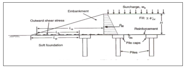
A typical example is a geosynthetic reinforced embankment whose construction on soft ground is illustrated below.
A rigid base underlies the clay forming the base of the reinforcement below a depth of 15 meters in the clay mass (Allen & Holtz, 1991). A prediction of the embankment behavior is the most critical element here. Feki, Garcin, Faure, Gourc, and Berroir (1997) argue that the underdrain shear strength of the foundation soil appreciates linearly as the depth increases. Of importance are the factors that determine the strength and behavior of the embankment (Leroueil & Rowe, 2001). The modulus of the geosynthetic reinforcement and the tensile strength of the underlying clay variably affect the behavior of the reinforced embankment. Below is a graphical representation of the relationship between pressures due to the embankment and the thickness of the fill, based on a study of soft clay soils (Leroueil & Rowe, 2001).
This geosynthetic reinforcement is initially subjected to increasing pressure with the entire load resting on the foundation. On continued application of force, a contiguous plastic failure occurs, shifting additional load to the synthetic reinforcement from the basement increasing the geosynthetic strain at a significantly rapid rate. However, stiff reinforcements can be exempted from succumbing to these strains (Fox, Rowland & Scheite, 1998).
An analysis of the behavior of the reinforcement indicates allowable design values for synthetic reinforcements. Varying the modulus by a rapid value has a marginal effect on the thickness of the fill material (Abrahams, 2009). On the other hand, a big reinforcement modulus significantly influences the embankment’s response. Extreme forces that strain the geosynthetic reinforcement beyond the material’s strain modulus leads to embankment failure which is illustrated in the diagram below.
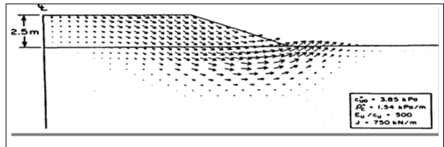
Different field velocity failure mechanisms exhibit different behaviors as illustrated below.
The restraining effect of the syntactic reinforcement is well illustrated by the dual arrows indicated above defined by a bearing capacity failure (Foose, Benson & Bosscher, 1996).
Many of the soft clays encountered in construction engineering are characterized by a high-strength surface crust. Analytically, the thickness of fill bears a strong relationship with the modulus of the synthetic reinforcement material. It is worth then analyzing the effect of reinforcements on the stability of an embankment (Foose, Benson & Bosscher, 1996).
Effect of reinforcement on stability
The key challenge here is to identify appropriate fill materials defined by the limiting method. The soil has to be identified with appropriate shear strength, embankment stability, and strong values. The orientation of the mobilization strength of the embankment is determined and the appropriate tensile force consistent with the factor of safety is determined (Fox, Rowland & Scheite, 1998). Variations on the factor of safety are critically analyzed about the strength of the soil. Empirically, the undrained shear strength of clay is calculated from the relation S= S (OCR) φ as illustrated graphically below (Abrahams, 2009).
Typical results are based on vane tests conducted to determine the vane shear strength values modeled after the vane’s strength soil profile. To mobilize the full mechanical and tensile strengths, the relation defines the time required to consolidate the full vane strength.
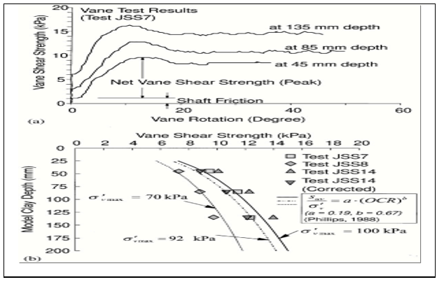
S and m are constants in the expression. A stability analysis based on the strength of reinforcement materials is here illustrated in the table below.
Eid, Stark and Doerfler (1999) and Foose, Benson and Bosscher (1996) argue that reinforcements significantly reduce soft soil lateral displacement and fill induced stresses on the embankment with the effect of reducing the lateral displacement on the overall mass.
As illustrated above, varying the shear stress directly varies the shear strain producing corresponding safety values. Appropriate variations affect the stability of the embankment concerning corresponding safety values (Tan, 1990).
The tensile stiffness of the reinforcement
A number of factors may influence the failure of a geosynthetically reinforced embankment as discussed above (Sharma & Bolton, 2008). One of these is the rapidity with which the construction is done. Rapid constructions cause the structure to reach its ultimate performance values giving in to applied loads, hence collapsing the whole structure (Tan, 1990).
A numerical analysis of an embankment’s failure is mathematically expressed as B ¼ 18 m, n ¼ 2. An equilibrium calculation of the geometry of failure has a direct relationship with the depth of the reinforced embankment and the type of fill materials applied in the reinforced structure. Moreover, fill materials are discussed elsewhere in the report. Research has established a thin relationship between the influence of the thickness of reinforcement and the thickness of the fill material. It has been demonstrated that the fill material is supported by geosynthetic reinforcement when the soft soil foundation reaches its ultimate contiguous plasticity level (Foose, Benson & Bosscher, 1996). Specific engineering values determine the response level of an embankment to applied loads. These values are calculated on the concept of undrained shear strengths, the width of an embankment, and other variables (Tan, 1990).
Centrifugal Tests
A typical centrifugal test is modeled as illustrated in the diagram below. The model is firmly held to the liner to prevent any horizontal disturbances during the test as the soft foundation settles. The friction between the liner and the soft soil was minimized by the use of nylon attached to the inside of the liner. A vertical pressure was consolidated using a consolidometer to a value equivalent 100 kilopascals. Experimental care was critical in the installation of the whole equipment and experimental variables such as clay before the clay was removed two days prior to the time of the centrifugal test.

The model is influenced by the symmetry of the embankment and all experimental procedures were followed in setting up the model. Analytically, the results were different results obtained by different environments during the experiment. The hydrostatic pore pressure was reached faster with soil foundation that was reinforced with wicks than one without as illustrated below (Sharma, Bolton, 2008).
It clearly demonstrated, as discussed elsewhere that rapid construction led to excess pore pressure being reached causing the clay foundation to significantly deform under pressures during the construction process. It was observed that lateral displacements occurred with different significant values were obtained for different different test soils (Terzaghi, Peck & Mesri, 1996).
Analytical methods
It is important to discuss at this point recent analytical engineering methods bearing in mind the performance of embankments on soft soils as discussed above. This is in addition to the fact that the load bearing capacity of an embankment is strongly influenced by shear stresses that act on an embankment due to the earth’s lateral pressures. Brokemper, Sobolewski & Alexiew (2006) see the bearing capacity and ability of an embankment to resist laterally deforming forces and earth pressures as being achieved by incorporating a basal reinforcement in the design and construction of a geosynthetically reinforced embankment. A number of failure mechanisms that modify the behavior of a geosynthetically reinforced embankment have been discussed elsewhere in this document (Brokemper, Sobolewski & Alexiew, 2006).
A number of technical considerations are made to prevent any failure mechanisms on reinforcement due to insufficient shear strengths within a reinforced embankment and fill materials. Horizontal movements of the soil, earth pressures, mechanical properties of the soft soil foundation, low mobilization mechanical properties such as tensile forces, strain-softening of the soft soil foundation, excessive horizontal and vertical displacements, the geometry of the soil profile, local yield, stiffness and depth of a reinforcement, and inappropriate use of tensile forces during a reinforcement process are some of the factors that influence the failure of an embankment (Brokemper, Sobolewski & Alexiew, 2006). Therefore a number of analytical methods used in the process include the limit equilibrium method, finite element method among others as illustrated below.
Investigating the Behavior of Clay Foundations
The kind of stress-induced anisotropy is significantly influenced by a one-dimensional consolidation.
Limit equilibrium method
These methods are critical in analyzing the entire failure mechanism of an embankment and the bearing capability and capacity of the structure, the slip cycle failure mechanism along the foundation of an embankment and failure mechanisms of fill materials, and lateral sliding within weak layers of the reinforced foundation.
It has been determined that the limit equilibrium method bears a close resemblance and relationship with other analytical methods. In this analysis, reinforcement on an embankment is represented by an externally acting or restoring force on the embankment. It is generally agreed that force due to the geosynthetically reinforced embankment acts laterally or horizontally on the failure mass. One such argument is based on the fact that the failure surface takes the shape of an arc in the foundation of the reinforcement while the foundation takes the design due to surcharged earth pressures (Terzaghi, Peck & Mesri, 1996).
To effectively counter the failure mechanism, the reinforcement for restoring the embankment structure is oriented along its original line of inclination and action. The maximum value yielded which are mathematical calculations of the factor of safety provides specific values for specific reinforcement stiffness without experiencing reinforcement breakages or failures. Therefore desired values can be calculated to effectively counter the failure of an embankment. To achieve the right values for the factor of safety, an analytical method for selecting appropriate reinforcement materials with sufficient mechanical properties and engineering characteristics are should be used. One such method is the finite element method (Terzaghi, Peck & Mesri, 1996).
The finite element method is characterized by in-depth analysis of the deformations or strains experienced for specific geosynthetic reinforcements. The reinforcements, in this case, constitute the soft soil foundation, the geosynthetic reinforcement, and the embankment fill that has been discussed elsewhere in the document. Analytically, it is important to note that the whole embankment structure’s mechanical behavior is heavily influenced by the relationship between these three elements and their interactions as a whole (Bathurst, 2007).
It has been established in the engineering and construction discipline that the finite element method provides sufficiently reliable data that qualifies any decision made on the behavior of embankments that are sloppy to be satisfactory. This analytical technique has been used in a number of fields by several researchers and in practical and theoretical situations to afford its intense application in sensitivity analysis and other analytical procedures in this field. Credit to this method is based on a number of numeral models developed for field studies. One of these is the nonlinear bar model among others (Bathurst, 2007).
This method model the behavior of granular soils that are applied in the construction of embankment fills and foundations that are never subjected to intense mechanical strains. However the need to establish accurately this behavior is influenced by the application of further tests and force when modeling the behavior of the soft soils under embankment loads. In addition to that, the method has the advantage of being able to model different soft soils with different conditions to establish the behavior of these soils under varying conditions (Bathurst, 2007).
Another modeling technique is the Viscoplastic design model. This model captures the time-dependent behavior that is exhibited by geosynthetically reinforced embankments particularly on soils that are retentive in nature. On the other hand, a creep-sensitive reinforcement should be modeled with a singly dimensioned bar when using the Viscoplastic design modeling technique. However, it is important to note that PVD reinforced embankments need to be given critical attention. When modeling them, an allowance should be given to allow for vertical drains to be modeled under the plain drain analysis.
Centrifugal Tests
Centrifugal Tests Setup
Developing embankments over peat case study
Case studies indicate a high success rate of constructing geosynthetically reinforced embankments over peat. One of them is the Bloomington road embankment consisting of a height of 5.9 meters fill material above a mechanically compressed peat material. It was observed that the thickness of the peat varied between two specific values of 5 and 7.6 meters. Further calculations indicated that the water concentration varied between 445 percent and 700 percent in value. A pair of peat surfaces were considered in the demonstration where geosynthetically reinforced materials were applied with different ultimate tensile strengths.
The first geosynthetic material’s ultimate tensile strength was 41 KN/m and the second one was 178 KN/m (Abrahams, 2009. It was demonstrated from the experiment that the second geosynthetic material drastically reduced the effect of lateral movements by a significant amount compared with the first set of geosynthetic material. It was analytically concluded that the use of geosynthetic materials for embankment reinforcement was significantly influenced by the design parameters of the material based on theoretical and practical values. It has been observed that irrespective of the ability for peat to retain large water content, yet if the foundation is appropriately reinforced, the ability of the foundation to withstand significantly large amounts of deforming forces is possible (Bouazza, Zornberg & Adam, 2002).
Creep in Geosynthetic reinforcements
The process of analyzing geosynthetic material properties must include a detailed analysis of the creep in these reinforcements. Detailed research and analysis have demonstrated that different geosynthetic materials subjected to different conditions exhibit different creep properties. These materials include geosynthetics made from polyethylene and other polymeric materials (Bouazza, Zornberg & Adam, 2002). The stress and strain of polythene-made geosynthetic material are directly related to the strain function of the material. These behaviors are time-dependent on soft soil foundations. One critical property of the geosynthetic material that significantly influences the final behavior of a reinforced embankment is the viscoelastic property (Bouazza, Zornberg & Adam, 2002).
The viscoelastic property decreases to a significant extent the amount of stability of a geosynthetically reinforced embankment in relation to the embankment’s height. That is the case with embankments that are constructed over soft soil foundations. Embankment construction on soft grounds takes a number of months to complete as compared to firm grounds. Therefore, the behavior of the embankment in terms of stability is time-dependent based on the viscoelastic behavior of the geosynthetic material. Different elastic properties for different geosynthetic materials exhibit different properties (Bouazza, Zornberg & Adam, 2002).
It is important to note that certain environmental conditions such as frost intensify the uplifting effect on piles and soft soil foundations in general. The variation in temperature therefore has a direct effect on the strength of a geosynthetically reinforced foundation. In addition to that, the dynamic behavior of the geosynthetically reinforced foundation of an embankment is strongly correlated to the effects of varying temperatures. Analytically, therefore, volumetric and linear changes are critically influenced by the changes in temperature with the overall effect noted in the nature of cracks and other fractures experienced on the geosynthetic material and other materials used in embankment construction.
It may be noted that temperature changes in the ground as discussed above have a strong relationship with the behavior of a foundation with time as illustrated below. Therefore, climatic variations influence to a critical extent the design factors and type of geosynthetic materials to use for a specific reinforcement when constructing an embankment.
Soil Mechanics
Mathematical Determinations
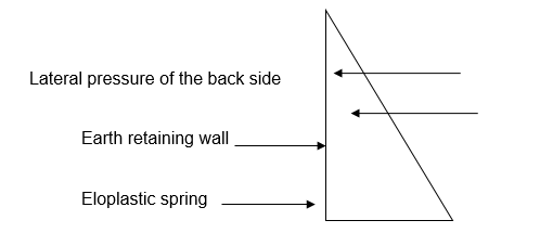
Modification of soil properties during excavations especially the earth retaining walls on soft soils causes the retaining walls to gain a level of rigidity required to withstand the soft soils and prevent the soil mass from crumbling. Motoi (n.d) discusses in detail the methods that are used to raise soil rigidity and presents a detailed analysis of soil improvement methods modeled after an earth resisting structure. Lateral pressures, of the backward side, the excavation side, and the pressures on the soil during the excavation process can be modeled and calculated as such Motoi (n.d). Below is an analytical model of the earth retaining structure.
Mathematical expressions
El (dy/dx) +Ey+Es+Esy= (p+qf) +…+1 is the differential equation that is used to calculate the lateral pressures on these earth retaining structures. Motoi (n.d) analytically details other soil improvement methods including the quicklime piles. Quicklime is arranged into cased holes in clay soils. Quicklime expands and reacts with the environment causing water to be absorbed in the process impressing the desired strength on the soil embankment.
Thus the ground strengthens achieving the desired mechanical properties for embankment construction. Motoi (n.d) outlines detailed excavation works by considering input lateral pressures, geological conditions of the soft soil, and analytically presents results from the reinforced model (Terzaghi, Peck, & Mesri, 1996). Terzaghi, Peck and Mesri (1996) argue that soils of any type are characterized by compression forces. The graphical representation below indicates the behavior of the depth of the foundation with the type of soil and the forces acting on the foundational soil.
These mathematical deductions enable construction engineers to determine structural alternatives to traditional reinforcements with specific focus on geosynthetic reinforcements. Geometric calculations help in identifying specific forces and pressures that act on walls when determining the internal and external stability of the walls. External stability is used to determine the conventional modes of embankment failures under the influence of gravity wall-designed systems and internal evaluations are used to determine the most critical factors specific to the internal stability of the reinforcement. Moreover, the cost of the reinforcement materials is influenced by depth of the reinforcement foundation and other cost-related variables.
Soil Improvement
It is important for soft soils to be improved before an embankment is constructed on them. Most soft soil foundations present the problem of high water content ratios that do not favor construction. In addition to that, the strength of reinforcement may be low while the lateral pressures due to the earth high cause them to be unsuitable for use as embankment reinforcements. However, a number of benefits are realized from improving the soft soil foundation.
These include minimizing land for settlement purposes, enhancing the mechanical properties of the soft soil foundation upon which the reinforcement is erected, mobilizing the shear strength of the soft soil foundation to prevent embankment failures particularly slip failures, and eliminating adverse environmental effects due to the foundation of the soft soil (Eid, & Stark, 1997). A number of techniques are used in the process. Soft soil improvement techniques include consolidation where the soft soil is improved through the technique of vibroflotation among others.
Another method is the vacuum improvement technique. Here vacuum pressure is applied on the soft soil foundation to particularly soils reinforced with PVD’s. The vacuum pressure significantly influences surcharge loading significantly reducing the surcharge height in the construction process. As an additional benefit, the isotropic effect of the vacuum pressure reduces the gradual effect due to failure from surcharged loads.
Several other methods for soil improvements exist and some offer temporary improvement solutions on the mechanical properties of the soft soil foundations. It is worth discussing them to compare their feasibility with geosynthetic materials
Geosynthetics for Soil Improvements
Geosynthetics is a technological advancement in the field of construction engineering that provides polymeric reinforcements as an economically feasible substitute to other technologies such as concrete and steel reinforcements. Holtz (2001) defines a geosynthetic material as “a planar product manufactured from a polymeric material used with soil, rock, earth, or other geotechnical-related material as an integral part of a civil engineering project, structure, or system” (Holtz, 2001).
The chapter provides a detailed analysis of geosynthetics with soil inclusions, geosynthetic properties and tests (Koerner, 1998). Tests include index properties, performance property tests and specifications. Environmental considerations, constructability requirements, reinforced slopes and other engineering considerations will be discussed in the course of the chapter (Koerner, & Hsuan, 2001).
Bygness (2007) defines geosynthetics as a combination of materials with different properties whose combined effect produces an engineering material with superior mechanical and chemical properties. These materials are characterized by high tensile materials which interlock into surrounding fill materials to form the final product. It is worth noting that geosynthetic is a generic name for geosynthetic materials used for civil engineering projects and geotextiles, geomembranes, and geogrids (Bygness, 2007).
The textile structure of geosynthetics is defined by extrusions and spans in the manufacturing process to where the mass of the fibers are then needle-punched before they form the final product. Gradually, the material goes through mechanical entangling welding the geosynthetic fibers together to form the final mass. On the other hand, geogrids are sometimes coated with polymeric materials to enforce other properties (Bygness, 2007).
Identification of Geosynthetics
Bygness (2007) details that geosynthetic materials are classified into a number of specific categories. These classifications fall into polymers, yarns, geosynthetic types, unit mass classifications, and physical properties. Physical properties used to classify geosynthetics include weight per unit mass, weight per unit mass openings, and geometrical thickness (Bygness, 2007).
Application
Geosynthetic materials are defined by their primary functions that include filtrations. Filtration is where other graded materials are replaced with granular filters as used in trenches and other points demanding their use. Fine grade soils are prevented from being moved into roads bases during construction since they possess the mechanical properties of being able to penetrate into underlying soft soils during construction work. Thus the roadway integrity is preserved in the process (Bygness, 2007).
Elias (2000) details that soft soil foundations and embankments can be reinforced with geogrid and geosynthetic materials to enable construction to take place. These embankments can be extended to stable and unstable slopes including very steep slopes that otherwise could be prohibitive with conventional materials and methods (Bygness, 2007).
Geosynthetic materials can also be used to encapsulate soils that are characterized by swelling and which display both mechanical properties that make construction prohibitive or expensive and lay severe mechanical penalties on traditional soil embankment techniques (Elias, 2000). Asphalt overlays are other areas of applications and waste containment, among others. A technique for reducing point stress on geosynthetic materials reduces to a significant extent puncture of the geosynthetic materials used in the construction of soft soil embankments (Koerner & Hsuan, 2001). A protective cushion is formed on these materials as discussed above, enabling them to offer a significant resistance to fracture and other unforgiving forces in the embankment process. It is worth noting that surrounding stones during embankments are some of the sources of point stresses and fractures that can be incurred on geosynthetic reinforcements during constructions (Elias, 2000).
Design and Selection of Geosynthetics
Brad names and impulsive methods were used in the design and selection of geosynthetics until geotechnical engineering methods were later on devised. Specific steps in design and selection include creating an original design that is tested against established specifications to determine if they are worth addressing an embankment need. (Koerner & Hsuan (2001) argues that practical engineering methods are used to identify their chemical and mechanical properties. Once the engineering properties have been established, a cost-benefit analysis is done against geosynthetic material properties to determine the best material that conforms to specified standards and which meets construction requirements (Koerner & Hsuan, 2001).
A careful field investigation forms an essential component of decisions made on the type of materials used in the process of design and construction purposes.
Geosynthetic properties
(Koerner & Hsuan (2001) argue that specific properties for these materials reinforce the fact that they are economically feasible building embankment materials. Geosynthetic mechanical properties are examined in detail against factors such as the density of the geosynthetic material, the weight of the material per given volume, the specific gravity of the material, the roll dimensions that are used to determine the material roll values, and the specific gravity of the geosynthetic material among other mechanical and chemical properties.
These properties are examined against standard test procedures and values that indicate the quality index of the material and its ability to survive penalties imposed by mechanical forces and chemical reactions during and after the construction process. These index values provide quality assurance values for the geosynthetic material and provide an insight into the mechanical behavior under embankment forces (Koerner & Hsuan, 2001).
These properties commonly referred to as constructability properties are fundamental in decision making when deciding on the kind of materials to opt for specific embankment constructions.
It is worth establishing insight into index properties. Index properties of these materials are determined from index tests. Index tests include grabbing tensile strengths and other mechanical property tests. Additional mechanical properties include load strain tests, tear and wear of the geosynthetic materials, values generated from seam strength tests, and material creep values.
Largely, other tests include the durability of the specific material used for embankments, its behavior under varying load and chemical conditions, the stability of the material under varying temperature conditions, biological resistance to organic decompositions, and hydraulic properties particularly the distribution of pores within the material. Each material must be tested for permeability to determine its behavior and its transitivity values (Koerner & Hsuan, 2001).
Performance Tests
Geosynthetic materials must satisfy certain performance criteria so as to identify the most appropriate material for soft soil embankments. It is important to test these materials against embankment design requirements and specifications. Specific performance indexes are used to compare results from test values to determine if they are satisfactory. Among the tests done include creep tests among others (Koerner & Hsuan, 2001).
Column Design Guidelines
Geosynthetics are primarily used to reinforce embankments on soft soil grounds, improve mechanical properties of soft soil foundations and on steep slopes and other sloppy areas, and manage earth forces due to pressures from earth walls and abutments through cost-effective methodologies which otherwise could not be cost-effective but rather prohibitive in all aspects of materials to use in the construction processes (Koerner & Hsuan, 2001).
In the construction process, before commencing construction, the engineer should keenly consider basic design approaches and the type of embankment to construct, keenly project the kind of embankment failures that might be expected and the best engineering design approach to overcome these issues. Some of the unsatisfactory failures that might occur if incorrect design embankments are done are illustrated below (Koerner & Hsuan, 2001).
Issues such as bearing capacity of the geosynthetic material, adequate sharing strength must be analyzed to establish the bearing capacity or limit of the material, and the geosynthetic limiting value tests are done to determine the extent to which they can be deformed. These tests enable the design and the construction engineer to find the most appropriate design approaches and materials to use to overcome geosynthetic deformations under stress and strain forces.
Geotechnical design procedures can be utilized in the process to gain an insight into accurate estimate parameters to incorporate in the design. Effective stress values and strain values calculated in the design process provide parametric values that qualify specific materials for use for specific foundational embankments on soft soils (Koerner & Hsuan, 2001).
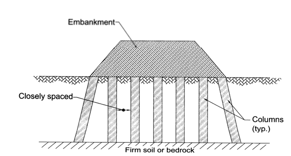
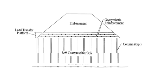
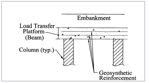
The following discussion takes us through design considerations for column-supported embankments. These designs detail load transfer mechanisms in soil embankments particularly vertically supported columns (Koerner, 1998).
Layers of geosynthetic reinforcement materials are used to transfer load within the locality of the embankment. The transfer, as is demonstrated consists of the bottom and top layers of column reinforcements that are used to distribute embankment loads thus preventing lateral spreading of the embankment loads.
Certain design criteria such as serviceability and the ability of the columns to support vertical loads due to embankment loads specify the design of the reinforcing material. The design factors giving specific emphasis and focus on load transfers such as lateral loads, the ability of the embankment to slide on top of the supporting columns, and the global stability of the whole system are some of the issues to consider during the design of the embankment and reinforcement materials. Koerner & Hsuan (2001) note that specific design considerations should be keenly applied especially when considering designs on solidly firm foundations.
That could also be in due consideration of geosynthetic load transfer mechanisms. Mechanical evaluations such as limit analysis and other considerations such as serviceability options, lateral and vertical strains, the load transfer platform, and the short term and long term load settlements after an embankment construction are serious considerations to make. Analytically, therefore, the whole system should be reinforced in a technical way to avoid unacceptable settlements in the long term. Poor and unacceptable settlements may come with undesirable mechanical and structural consequences. An illustration of an embankment on soft and firm foundations is provided below.
Analytically, it is feasible to consider the general steps involved in the design process of column-supported embankments. These steps are vital for the design engineer to consider providing the most cost-effective design besides other accruing benefits. These steps include a keen evaluation of columns spacing to effectively accommodate lateral and vertical shear stresses and other forces, use mathematical methods of determining or calculating the amount of load that the columns can withstand, consider geotechnical information and data in determining the specific geosynthetic columns for reinforcement purposes. These considerations must reflect the geotechnical requirements of the site to be reinforced (Bressi, Zinessi, Montanelli & Rimoldi, 1995).
The next step is to determine column spacing in addition to column mechanical abilities to withstand specific loads and forces exerted in the reinforcement, determine the aggregate number of columns required, and keenly select the catenaries based on the data made available from the construction site.
Reinforcement requirements should be determined in the process, the global stability of the embankment should be determined, and construction design in the form of a diagram detailing the design mode. Design and construction specifications are then determined. Several considerations about the failure limits are here illustrated as being among the most important factors to consider in the design process. To avoid undesirable consequences, geotechnical design principles ought to be adhered to in the process. In addition to that, geotechnical considerations of the serviceability of the design are illustrated also (Bressi, Zinessi, Montanelli & Rimoldi, 1995).
Serviceability illustration, from: Geosynthetics Classification
Supporting Pillars
One of the most fundamental elements to consider in the construction process of an embankment is the design of supporting pillars. Therefore columns selected for the reinforcement are usually based on material properties that include lateral, vertical, and other loads that the embankment is always subjected to. A cost-effective analysis is conducted in the process to evaluate the most cost-effective method and selection materials to use in the embankment construction (Bressi, Zinessi, Montanelli & Rimoldi, 1995).
As a specific engineering consideration for each column, the surcharge loads and the total tributary area of the support columns are determined in the process. It is important to determine vertical forces on the columns based on the tributary areas which can either be hexagonal, triangular, or squared. These considerations are typically illustrated below (Koerner, 1998).
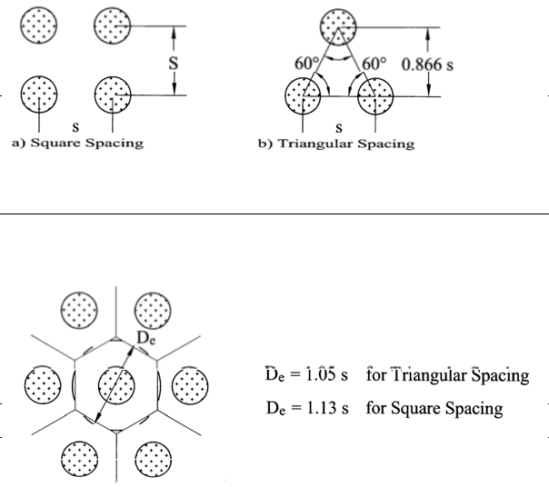
Mathematically, these considerations are done and analyzed based on the relation here expressed mathematically, Qr = π (De/2)2 (γH + q). The equation provides a relation between the vertical design loads and the tributary area of the column effects as mentioned above. The vertical height of the reinforced embankment, load surcharges that can either be live or dead loads, and the unit with the specific embankment. Thus, the column layout is demonstrated in the diagrams above.
Stability of the edge
To ensure an embankment remains stable and has does not indicate any potential for failure due to lateral forces, it should be designed so as to extend a little bit outwards. The extension is defined at the edge of the column of the design to overcome any instability differentials due to embankment settlements that can be short-term or long-term. Therefore, the edge stability should be vigorously checked and evaluated for their level of stability and ability to withstand a combination of forces that may be brought to bear on these masses (Koerner, 1998).
Several standards against which the analysis is conducted include the British SB8006 standards among others. Mathematically, edge stability can be analyzed using the relation stated here as Lp = H (n-tanθp). Each of the variables represents a specific property in the embankment material as here discussed. From the equation, n represents the inclination of the embankment; tanθp is the tangent of the angle measured from the vertical plane and between the crest and the outermost column while ϕemb is the angle of friction determined on the embankment fill as illustrated in the diagram below.
Lateral Spreading
Lateral spreading is another rigorous method of determining the mechanical abilities of the geosynthetic material to overcome lateral forces that may be globally spread on an embankment (Koerner, 1998). These lateral forces, also referred to as horizontal forces are calculated based on the mathematical relation, Tls = Ka (γH + q) H/2. Issues such as the minimum length of a reinforced embankment are calculated based on the relation, Le = Tls /[0.5 γ H(ciembtan ϕemb)]. The whole process is illustrated below.
The above demonstration is based on the BS8006 standards.
Load Transfer Considerations
A number of layers are used to reinforce the soft soil mass based on a number of methods. One of the methods, known as the Guido method, is technically significant and feasible in identifying the load transfer mechanism involved in the design between the top and bottom of the embankment. Load distribution based on the multilayered approach ensures a fair and uniform distribution through the body of the embankment. It is worth noting that the embankment creation is based on a three-layered platform. In addition to that, the layers consist of a design ratio specified by the thickness of the platform and the depth of the
Tension membrane
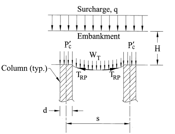
The Tension membrane theory describes load distribution mechanisms on a geosynthetically reinforced embankment. The load distribution relies on the thickness of the embankment, the vertical loads exerted on the soils and embankment mass, and the amount of soft soil distributed within the surcharged loads.
The theory is described in the illustration drawn below. It is worth noting that the height of the embankment is defined in the illustration by the letter H, while the diameter of the column is described by the letter d, the stress exerted in the vertical direction by the embankment is indicated by the letter p, q describes the surcharged loads, while s is descriptive of the center-to-center spacing of the columns, T describes the tension existing in the reinforcement extension, and w describes the load supported by the reinforcement in the vertical direction. Among a number of theories that can e used to determine the tension experienced on the geosynthetic material used in the reinforcement is a described above and illustrated in the diagram below (Berg, Allen & Bell, 1998).
The beam method
Among the other theories as highlighted above used to describe the behavior of beams under loading conditions and specific design considerations for supporting beams with respect to the distribution of load under the geosyntetically reinforced embankment is the beam method. This method is based on a number of assumptions. One such assumption is that the thickness of the load transfer platform is a differential value of the spacing between the columns and the diameter of the supporting column. Another assumption is based on the smallest number of geosyntetically reinforced materials that are applied into three layers for the load transfer platform.
Other engineering assumptions provide appropriate estimates of the distance between reinforced layers as being six inches, identify and define the specific fill materials used in the platform used for load transfer, and the fact that the reinforcement can only be subjected to an initial strain equivalent to five percent of the overall strain values. The theory specifically assumes that the load transfer within the reinforced embankment between the top of the reinforced platform and the supporting columns is in the vertical direction. That implies that the load can be significantly distributed to the bottom of the reinforcement, shifting it appropriately. It is assumed that besides other reinforcement applications, another role of the reinforcement is to offer strong support for the wedge of the soft soil below the arch of the embankment (Berg, Allen & Bell, 1998).
Mathematically, there is a strong relationship between the load that is carried by each specific layer of the embankment and the spacing between the columns and the vertical space existing between embankment erections. Besides that, there is a strong relationship between the mechanical properties of the soil mass, tensile, and other mechanical properties of the soft soil. In addition to that, the platform fill significantly influences the type and specific amounts of load supported by each layer of the reinforcement. Specific layers offer specific support to specific types of load distributions within the reinforced embankment. Load transfer mechanisms, therefore, depend on the column design end elevation of each column. These designs include square and triangular column design spacing.
The modified design method
In addition to the methods detailed above, the modified design method is based on numerical modeling where the above procedure is altered based on an increase of additional layers of reinforcements. This design incorporates a catenary designed to support soft soils from below the arch. The mathematical relationship between the vertical loads applied on the catenary with a triangular spacing can be expressed in the relation, WTn = hn γ/ 3. WTn represents the volume of the supporting pyramid, and subsequent factors represent the surface area of the catenary, and the surface area of the density of the fill material used in the reinforcement.
Other forces that play a critical role in the design of the reinforcement include the tensile forces argued form the basis of the membrane theory. This theory is used to determine the existing tension in the reinforcement based on the mathematical relation, TrpC = WTC Ω D/2 (Berg, Allen & Bell, 1998).
Geotechnical Engineering Procedures
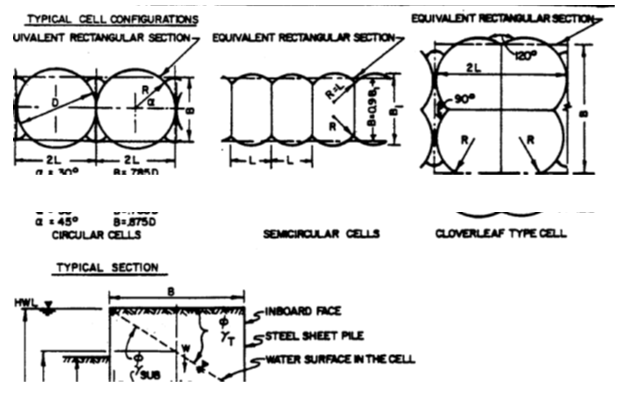
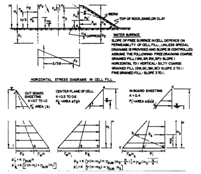
Unified Facilities Criteria (UFC) (2005) provides a detailed analysis on shallow and deep foundations, other soil stabilization methods, dewatering and other approaches for controlling groundwater. Grouting methods and equipment are discussed in detail here. Design criteria for cellular cofferdams are discussed as illustrated below (Koerner, 1998).
Excavations
Daniel, Koerner, Bonaparte, Landreth, Carson, and Scranton (1998) specify a number of methods that are used to determine the stability of excavation as spanning the open and braced methods for soft soils particularly soft soil foundations. Each of these methods provides specific levels of stability on slopes defined by different structural mechanisms. The first method is characterized by slope stability that is defined by stable side slopes while the second method is defined by lateral reinforcements (Daniel, Koerner, Bonaparte, Landreth, Carson, and Scranton, 1998). They argue that both slopes experience lateral and vertical pressures that are exerted by the earth on the soil mass.
Analytically, therefore, it is important to select an appropriate excavation method depending on the mechanical strength of the soil, the soil type, and the level of the ground water that significantly influences the behavior of the soil it is absorbed into. Daniel, Koerner, Bonaparte, Landreth, Carson, and Scranton (1998) note that appropriate techniques for protecting slopes in the design and construction process should be selected bearing in mind the structural stability of the ground, the mechanical properties of the soft soil, vertical and lateral forces associated with the movements of the ground and the effect of such movements on the reinforced embankment structure (Bouazza & Amokrane, 1995).
Open cuts
Berg, Allen & Bell (1998) argue that open excavations are influenced by the depth of the slope and the depth of the excavation. The depth of the excavation influences the stability of the clay soil. In addition to that, the depth of the cut made in the soil, the mechanical strength of the soil in terms of tensile strength, brittleness, and other mechanical properties are directly influencing factors in the design and construction of the embankment. Other geotechnical issues include the slope of the excavation, the slope of the slide, and specific construction procedures used in the embankment of the construction (Berg, Allen & Bell, 1998).
Vertical Cuts
Cuts in clay soils that are classified as soft soils remain persistent for some time before the soil mass collapses or failure occurs. It is important to note that the shares strength of soft soils deteriorates progressively leading to the collapse of the land mass during the excavation process. Different clay soils and other soft soils characterized by different mechanical properties such as share strength of the soft soil offer varied resistance to vertical cuts or penetration. The vertical penetration process can be rapid or slow depending on the soil type and mechanical properties (Bouazza & Amokrane, 1995).
Trenching
Varying trenching requirements significantly influence to a great extent the design of the shoring system due to the direct influence of ground water and other geotechnical conditions that bear a significant relationship with the design of the system (Bouazza & Amokrane, 1995).
Site investigations form one of the fundamental elements and preconditions to the design and construction of an embankment or excavation. Site exploration is characterized by forces and loads that cat on the embankment or excavation walls and overall structure. Of typical interest are the factors that influence the stability of the structure of a trench. These factors are summed up in lateral forces that are exerted on specific walls and corresponding effects of these forces (Bathurst, Miyata, Nernheim & Allen, 2008).
A number of factors influence the stability of a trench, besides the nature of an embankment and other factors involved in the process. These are external and internal factors. External factors include a surcharge that is o the surface of an embankment, mechanical vibrations due to movement of machinery in the construction process, the extent to which ground water sips into the structure, and the flow rate and strength of the surface water (Bouazza & Amokrane, 1995).
Surcharged loads influence the stability of a trench as a result of additional weights exerted between the trench excavation and the angle of inclination between the ground and probable planes of failure in the cutting process (Bouazza & Amokrane, 1995).
The movement of machinery and other above-ground activities such as blasting and related applications of loads and impact forces have the potential to cause long-term damage to brittle soils such as soft and clay soils (Bouazza & Amokrane, 1995).
The strength of the underlying soil properties can be altered by the existence of flowing surface or ground water. Flowing water significantly alters the strength f the soil making it weak with the potential probability to be overcome by applied loads and other forces (Bouazza & Amokrane, 1995).
Typical analyses of some of the factors that influence the stability of the soil during excavation in problem soils are tabulated below.
From: Unified Facilities Criteria (UFC).
Factors influencing excavation stability
From: Unified Facilities Criteria (UFC).
From: Unified Facilities Criteria (UFC)
It is important to briefly discuss support systems that are used during the excavation procedure. These methods include the trench shield method is where rigid steel structures are used in the process, trench timber method, where braces and other equipment are used in the process, and telescopic shoring method among other methods. In comparison with geosynthetic materials, these materials are prohibitively expensive to buy for construction purposes.
Excavation monitoring
Analytically, all forces that may be perceived to act on an embankment, both theoretical and practical, are incorporated at the design stage using specialized analytical methods and specialized ground support methods. These may include electro-osmotic techniques, vacuum wells among others. In addition to that, monitoring should be a continuous process particularly during the excavation period extending to populated areas to ensure minimum disturbance to the surrounding. Other monitoring tools include factors of safety specified under established standards. Some of these requirements include the structural behavior of the banks, the length of and specific support mechanisms, material used in the process, and the site for trench excavations. The process is continuous and iterative and is always evaluated to ensure minimum safety and other engineering requirements are met.
Having discussed in detail a number of requirements for typical excavation scenarios and the monitoring approach, it is important to discuss fill and other fill variables.
Fill
Fills come under various descriptions and types. These categories include hydraulic fills, industrial and a number of domestic wastes, slag, and a number of other fill materials. Soft soils and clean sand among other construction materials are used in the filling process and provide modifications of the properties of embarked soil in soft grounds. It is important to carefully consider appropriate methods for applying fill into foundations and other areas of a reinforced structure. In addition to that, the importance of investigating fill compaction requirements that help modify geosynthetically reinforced embankments.
Appropriate investigations should be done to identify the properties and availability of specific types of fill materials, specific compaction details on these materials, equipment used for compaction, and compaction procedures.
Compaction specifications are influenced by a number of factors. These include specific characteristics of the fill and the structure to be set up within a specified environment, the ability to compact a material to the desired density for use within a specified structure, engineering specifications particularly for soft soils and all types of clay, and the need to use a specific type of fill material that exhibits the tendency to sag and behave desirably under specific forms of load.
Backfill
It is important to conclude this section with a brief discussion on backfilling mechanical tests. Appropriate application of backfills mobilizes the structural strength of an embankment to gain the desirable structural strength of an embankment that is geosynthetically reinforced. A number of techniques are applied here. These tests and properties are influenced by areas of applications such as critical areas. Critical areas are those that are under buildings and other structures and service conduits among others. Others are differential settlements where cut and cover structures experience down drags and roofs. Some of the tests done on the backfills include pressures due to the earth, surcharged pressures due to the earth’s lateral and vertical loads and impact forces, and pressures induced through compactions.
Backfill evaluation criteria
In addition to the above discussion, it is important to consider engineering properties of backfill materials to determine their mechanical properties when used to fill embankments and provide necessary modifications of embankment material properties. These engineering properties are determined by collecting specific samples after conducting intense explorations and subjecting them to laboratory tests to identify their mechanical properties for engineering purposes (Palmeira, Tatsuoka, Bathurst, RStevenson & Jorge, 2008).
One of the critical components in the laboratory testing processes is the identification and classification of soils with distinct engineering properties. These properties specifically for soft soils are influenced by the plasticity of the specific soil type and grain flow of the soils among other properties (Blume, Alexiew & Glötzl, 2006).
(Palmeira, Tatsuoka, Bathurst, RStevenson and Jorge (2008) argue that among the tests done on these materials include compaction tests to generate compaction values specifically for soft soils, shear strength testing to determine water content and other related properties when used in soft soil foundations and embankments. Other tests include permeability tests that are done to identify characteristic properties of a backfill in influencing the flow of water through the reinforced structure and the ability of the backfill to modify other mechanical properties of the reinforcement. Other tests include swelling tests, consolidation tests, and the behavior of slaking tests (Blume, Alexiew & Glötzl, 2006).
Lightweight fill
Foundation stability bears a strong relationship with applied loads and stress levels. The stability of soft soil embankments largely depends on the weight of fill materials with a compaction density significantly lower than that of soil commonly applied for embankment construction. An example of lightweight fill materials is illustrated in the table below (Leroueil & Rowe, 2001).
Source: Unified Facilities Criteria (UFC).
Lightweight fill materials are disadvantaged by cost and design problems. These materials have a low crashing strength and are biologically degradable.
The application of the materials tabulated above significantly improves the pressure of the underlying soft soil foundation thereby reducing the effect of pressure on the same foundation. The materials are used to replace to a significant extent the excavated soil from the intended construction site. The advantage of this method is that the lightweight fill materials are easily accessed at low costs and in sufficient quantities to guarantee their use on the construction site. However, the unavailability of ground to dispose of the excavated soil is a critically limiting issue in the use of this method.
Removal and replacement
Removal and replacement is a simple approach where the problem soil is removed and replaced with desired quality materials. The replacement method is appropriate for highway embankments and structural foundations for buildings depending on the geotechnical demands of the environment (Terzaghi, Peck, & Mesri, 1996).
Conclusion
Geosynthetic reinforcements are considerably cheaper as compared to traditional reinforcement materials and methods. Theoretical values analytically obtained through different analytical methods indicate that field values differ by a significant extent from field values. That has been attributed to a large extent the working stress conditions and other forces during construction process. In addition to that, embankment failure is significantly influenced by the height of the geosynthetic reinforcement on soft soil foundations.
One of these methods incorporates the mechanism of placing a layer over the soft soil to mobilize tensile forces and mechanically confine and increase the soil tensile strength reducing lateral distortions and shear stress levels. The magnitude of the reinforcement impact bears a close relationship with the embankment geometry, embankment safety, and the level of stiffness of the embankment. When the depth of the soft soil foundation increases, the strength of the soil increases increasing the strength of the soil and the stiffness of the embankment appreciates linearly. In addition to that, the use of reinforcement strain and strengths can be mobilized by the use of viscoelastic geosynthetic materials. A number of tests have to be done on geosynthetic materials before they qualify for reinforcement purposes.
These tests include compaction tests to generate compaction values specifically for soft soils, shear strength testing to determine water content and other related properties when used in soft soil foundations and embankments. Other tests include permeability tests that are done to identify characteristic properties of backfill in influencing the flow of water through the reinforced structure and the ability of the backfill to modify other mechanical properties.
During the design process, geosynthetic mechanical properties are examined in detail against factors such as the density of the geosynthetic material, the weight of the material per given volume, the specific gravity of the material, the roll dimensions that are used to determine the material roll values, and the specific gravity of the geosynthetic material among other mechanical and chemical properties. These properties are examined against standard test procedures and values that indicate the quality index of the material and its ability to survive penalties imposed by mechanical forces and chemical reactions during and after the construction process.
These index values provide quality assurance values for the geosynthetic material and provide an insight into the mechanical behavior under embankment forces. Climatic conditions such as areas that experience severe frost and other extreme weather conditions should be thoroughly considered when selecting a geosynthetic material and when designing a geosynthetically reinforced embankment.
References
Abrahams, M., 2009. A Parametric Study Leading to Software Analysis Revealing an Equation for the Preliminary Design of Reinforced Earth Embankments. Web.
Allen, T. M. & Holtz, R.D., 1991. Design of Retaining Walls Reinforced with Geosynthetics, State of the Art Paper, session 8A on Earth Reinforcement, Geotechnical Engineering Congress 1991: Geotechnical Special Publication, 27 (II), pp. 970-987.
Bathurst, R.J. 2007. Geosynthetics Classification. IGS Leaflets on Geosynthetics Applications, IGS Education Committee. Web.
Bathurst, R.J., Miyata, Y., Nernheim, A. and Allen, T. M. 2008. Refinement of K-Stiffness Method for Geosynthetic Reinforced Soil Walls, Geosynthetics International, 15(5).
Berg, R.R., Allen, T.M. and Bell, J.R. 1998. Design procedures for reinforced soil walls- A historical perspective. 6th International Conference on Geosynthetics, IFAI, Atlanta, Georgia, USA, 2,pp. 491-496.
Blume, K., Alexiew, D. and Glötzl, F. 2006. The new federal highway (Autobahn) A26 in Germany with high geosynthetic reinforced embankments on soft soils”, Geosynthetics, Milpress, Rotterdam, pp. 913-916.
Bouazza, M., Zornberg, J. G., & Adam, D. 2002. Geosynthetics in Waste Containment Facilities: Recent Advances. Keynote paper, Proc. Seventh Intl. Conf. on Geosynthetics, Nice, France, A.A. Balkema, 2. pp.445-510.
Bouazza, A. & Amokrane, K. 1995. Granular soil reinforced with randomly distributed fibres. 11th African Regional Conf. on Soil Mech. & Foundation Eng., Cairo:pp. 207-216.
Bressi, G., Zinessi, M., Montanelli, F. & Rimoldi, P. 1995. The slope stability of GCL layers in geosynthetic lining system”. 5th Intl. Symp. on Landfills, Cagliari 1, pp 595- 610.
Brokemper, D., Sobolewski, J. & Alexiew, D. 2006. Design and construction of geotextile encased columns supporting geogrid reinforced landscape embankments; Bastions Vijfwal Houten in the Netherlands, Geosynthetics, Milpress, Rotterdam, pp. 889-892.
Bygness, R. 2007. Using geosynthetics for avalanche protection in northern Iceland, Geosynthetics, 25(5) pp. 16-20.
Byrne, R.J., Kendall, J. & Brown, S. 1992. Cause and mechanism of failure, Kettleman hills landfill B-19, Unit 1A. Stability and Performance of Slopes and Embankments, ASCE. Geot. Sp. Publication 31, pp.1188-1520.
Daniel, D. E., Koerner, R., Bonaparte, R., Landreth, R., Carson, D. and Scranton, H. 1998. Slope stability of geosynthetic clay liner test plots. J. of Geot. and GeoEnv. Eng. 124(7), pp. 628-637.
Eid, H.T & Stark, T.D. 1997. Shear behavior of an unreinforced geosynthetic clay liner. Geosynthetics Intl. 4(6), pp. 645-659.
Eid, H. T., Stark, T. D. & Doerfler, C. K. 1999. Effect of shear displacement rate on Internal shear strength of a reinforced geosynthetic clay liners. Geosynthetics Intl. 6(3), pp. 219-239.
Elias, J. M. 2000. Properties of the new laser welded geogrid made of extruded bars ,Euro Geo 2 Conference, Bologna, Italy.
Feki, N., Garcin, P., Faure, Y.H., Gourc, J.P. and Berroir, G. 1997. Shear strength tests on geosynthetic clay liner systems. Proc. Geosynthetics 97, Long Beach 2, pp. 899-912.
Foose, G. J., Benson, C. H. & Bosscher, P. J. 1996. Sand reinforced with Shredded waste tires. J. of Geot. Eng. 122 (9), pp. 760-767.
Fox, P. J., Rowland, M.G. & Scheite, J. R. 1998. Internal shear strength of three Geosynthetic clay liners. J. of Geot. and GeoEnv. Eng. 124 (10), pp. 933-944.
Frobel, R. K. 1996. Geosynthetic clay liners, part four: interface and internal shear strength determination. Geot. Fabric Report 14(8), pp. 20-23.
Holtz, Robert, D. 2001. Geosynthetics for Soil Reinforcement. University of Washington, Seattle, Washington. Web.
Koerner, R. M., 1998. Designing with Geosynthetics, 4th ed., Prentice-Hall, New Jersey, U.S.A.
Koerner, R. M. & Hsuan, Y. G., 2001. Geosynthetics: Characteristics and Testing, In Geotechnical and Geoenvironmental Handbook, R. K. Rowe, Editor, Kluwer Academic Publishers.
Leroueil, S. and Rowe, R. K., 2001. Embankments over Soft Soil and Peat”, In Geotechnical and Geoenvironmental Handbook, R. K. Rowe, Editor, Kluwer Academic Publishers.
Motoi, Y., n.d. Soil Improvement during Excavation in Soft Ground and Development of Analysis Method for Earth Retaining Structure. Obayashi Corporation, Tokyo, Japan.
Palmeira, E. M., Tatsuoka, F. Bathurst, R. J., Stevenson, P. E., Jorge, G. 2008. Advances in Geosynthetics Materials and Applications for Soil Reinforcement and Environmental Protection Works. Web.
Sharma,J.S., Bolton, M.D. 2008. Centrifugal and numerical modeling of reinforced Embankments on soft clay installed with wick drains. Geotextiles and Geomembranes. Swiss Federal Institute of Technology, Zurich, Switzerland Cambridge University Engineering Department, Trumpington Street, Cambridge CB2 1PZ, UK 19, pp. 23-44 Tan, S. L., 1990. Stress-Deflection Characteristics of Soil Soils Overlain with Geosynthetics, MSCE Thesis, University of Washington, Seattle, 146 pp.
Terzaghi, K., Peck, R. B. and Mesri, G., 1996. Soil Mechanics in Engineering Practice, 3rd ed, Wiley.
Unified Facilities Criteria (UFC). 2005. Geotechnical Engineering Procedures for Foundation Design of Buildings and Structures. Web.