Introduction
The idea behind this project is to come up with a system that will be a substitute for the use of human life in cases where explosives or hazardous materials are concerned. It is rather practical and moral to use robots to perform hazardous tasks instead of using human lives [17]. The system in mind here is a wireless robotic car. A robot as defined by the Macmillan English Dictionary For Advanced Learners is a machine that works by itself [10].The cars design is such that its inherent attributes guarantee humans minimal or no exposure to such dangerous and hazardous materials. The navigation actions of the wireless robotic car are remotely influenced by graphical user interface running on a computer. GUI are friendly user interface as they involve issuing simplified command protocols while a live video camera relays back to the computer. Radio frequency will relay communication signals between the remote computer and robotic car. The PIC microcontroller will control the motions of the robotic car and thus will determine the signals relayed by the transceiver. H-bridge mediates the PIC and motor because of the limited microcontroller current supply. The wireless robotic car communication s will be effective within radius of 100m from the remote computer. The live video camera has night vision capacity [6].
Project Scope
The project assumes that society is already facing dangers arising from use of explosives and radioactive materials. In situations where a person drives into a danger zone, wireless controls with remote assistance can aid navigate out of the risk. The robotic car will be navigated out remotely. A robotic car is fitted on the wheels with live video relay gadgets that provide the remote navigator via the PIC microcontroller to visualize the immediate environment. This facility allows the remote navigator circumvent obstacles while driving away from danger places. This resembles closely the satellite tracking as well as track and trace technologies in the logistics management, especially in long distance shipments. Longer life batteries fitted in such a robotic cars will allow prolonged navigation time with the remote navigator before battery runs out. Another advantage in the robotic car is its wireless communication with a remote navigator. Wired connections can easily get entangled result to the robotic car enable to move. This introduces a new problem especially when the person driving the car enters a danger zone [12].
Robotic cars application in danger scenes is an imperative real life option. With the increasing concerns of occupational health and safety, any imminent threat to human life or pristine environment is a major concern. For instance, with the increasing need for developing economies to meet energy demands for household and industrial processes, more and more nuclear plants have been constructed. However, nuclear waste is also pilling up and sites have been set aside to contain the waste. Nuclear energy waste is put in tight lid containers that are either buried underground away from human contact. Nuclear waste is non-biodegradable thus; stockpiles will continue to increase as more nuclear energy is produced. Nuclear energy accidents present far reaching adverse effects on both human and environment. These hazards are both proximate while others manifest themselves in the future. Dangers associated with radioactive materials include health complications such as cancer and general body deformations. Radioactive substances include uranium, strontium, plutonium, cesium, iodine (Environmental Yellow Pages Inc., 2010). Explosives can cause great damages and even death. However, use of radioactive elements to provide energy to power economic growth is a trade off the dangers that the citizenry are exposed to. A case in point is the Chernobyl nuclear accident in Ukraine in April 1986 that led to death of 36 people mainly fishermen. These further contaminated the reindeer meat in Scandinavia. In a accident nuclear scenes use of the robotic car is most likely than committing human life. Robotic cars are remotely monitored through a radar screen as commands are issued via the PIC microcontroller to effect a rescue mission or do forensic analysis on the disaster scene. Thus, it can act as a rapid response strategy while planning on a more comprehensive operation in a disaster scene. Rapid response strategy forms an important component of the disaster preparedness and management. During the forensic analysis, the robotic cars may be fitted with sample collection devices as well as data collection devices that take measurements. This can provide information for decision making and building effective strategies for the comprehensive operation. Robotic cars can monitor sites with nuclear waste containers to ensure radiations do not leak into the environment [16].
Robotic cars fitted with censors can be deployed in landmine areas to spot the mines rather than risked human life. Mines easily trigger of if disturbed. Using global positioning systems and GPS devices fixed on robotic cars to get their exact spots and later to be extracted with more precaution.
Literature Review
The first step taken in this project was an exploration of the different and latest technologies and coming up with the ideal methodology to use. At the very heart of this project is the PIC Microcontroller this is because it enables a user to control the direction, movement and speed of the robotic car. The PIC Microcontroller for this project must have a Pulse Width Modulation capability. This capability will allow the integration of a radio control system for the car. For a PIC microcontroller with Pulse Modulation ability observation made is that, the more the electric power that goes through it the width of the modulation widens further. The purpose of the modulation is to generate control logic signals that enable direction and speed control of the report. The system will function in one of two states; these are too retracting and full extension. The state at which the system is in at a particular instant will be dependent on the radio control system of the car [5].
It is fundamentally basic to install an H-bridge in between the PIC microcontroller and the motor of the car. An H-bridge according to the article “H- Bridge” is a circuit that applies voltage to be applied from both of its sides (2010).The H-bridge in this context ensures that instructions from the microcontroller are executed as well as ensures that there is enough current to drive the motor of the car. An H-bridge for this project must allow voltage application from both of its side in order to ensure back and forth movements, as is the case in robotics. As Wilmhurst points out an H-bridge at its most basic level contain four switches, say switches s1,s2, s3 and s4 (2007). At any given instance, a combination of these switches can open or close allowing voltage to move in a given direction and the system to move in a particular direction. Such planning of the H-bridge circuitry will affect the amount of voltage going through the system. To illustrate let us assume that the system programming is such that switches s1 and s4 trigger forward movement while switches s2 and s3 trigger backward movement. Then notice that, after opening s1 and s4, and closing s2 and s3 the voltage moves in one direction causing forward movement whereas after open s2 and s3 and closing s1 and s4 closed the voltage moves in the reverse direction that in turn causes backward movement. In the robotic car, the H-bridge comes in handy to either open or close the breaks of the car. Huang advances the importance of the H-bridge in this project by pointing out that, H-bridges are suitable for situations that demand the use smaller physical sizes and a fast rate of opening and closing switches (2005). This is the case in this project, as voltage consumption should be small whereas detection of explosives and radioactive materials should be fast and accurate [8].
Video streaming technology is also an integral part of this system. Video streaming will ensure the easy navigation of the robot car, reduce the time the car takes to reach its target destination and inform the human controller of the car’s position. The proper camera for this application has have night vision capability and fitted with a CCD sensor as those used in the security sector. According to the article “charge-coupled device”, CCD stands for charge-coupled device (2010). The sensor’s function in this case is to detect radioactive materials and explosives while night vision will enable the car’s use in dark places where visibility is of the utmost importance and lights are not required. The camera in this application will only be able to monitor the robot car within a radius of 100 meters [2].
Project Plan
This project will be a success if it achieves its objectives. In order for it to succeed, it is fundamental that it has a project plan. The project plan for this project contains five phases, that are, project development phase, project design phase, construction phase, testing phase and the marketing phase.
The project development phase of this project is the most imperative as it will set the major objectives of the project as well as define comprehensively the course of work thereof. Objectives specifically show the study intentions of the project proponent. Thus will mainly reflect what is anticipated in the successful completion of the project. Objectives should be S- M-A-R-T (Oso & Onen, 2005). The S- M-A-R-T acronym stands for specific, measurable, attainable, realistic and time bound. An objective is specific when it clearly and explicitly communicates about the what, where, when and how the situation will be changed by the project. These form the intended products of the project. The objective should be brief and straight to the point. An objective is measurable when it is able to quantify targets and/or benefits quantitatively or qualitatively. The project outcomes observed or measured in this case. When stating the objective active verbs (to describe actions) useful for this, such as determine, describe, ascertain, establish and so on. Other recommendations include the use of words without terminal characteristics such as know, comprehend, feel, enjoy master and so on are discouraged. An objective is attainable if the projective can achieve set objectives based on available resources and capacities at the disposal of the project. Two perspectives of attainable objectives are feasibility and degree of complexity while pursuing to achieve them. An objective is realistic if the project proponent is able to achieve his desires. An objective is time bound when it is achievable within feasible set period. There must be set time within which the project should be undertaken and a report submit. Objectives that achievable within periods are to be avoided. The tasks in this phase are undertaken chronologically and in a sequence because a task depends on the completion of the previous task. That is, in order to proceed to the second task, task one has to be completed and in time, while task two has to be completed and in time as well, before you proceed to the third task and so on.
The project design involves delving into research about existing approaches to the design of the system. This will involve assessing the theoretical and conceptual frameworks. Out of this phase will come out a final design that has no anomalies of any nature. Tasks in this phase are performed sequential manner as described above to make the design process more productive and less difficult.
The construction phase will involve hardware and software development. During this phase multitasking is possible and convenient e.g. construction of a PCB board and microcontroller programming can be done simultaneously avoid the unnecessary wait if the tasks are done one after the other. Proper coordination is important at this phase to avoid mishaps that lead to extra and unnecessary expenditures.
The testing phase will involve carrying out tests on the individual hardware and software components of the system with an aim of determining whether they are functioning well. Test the overall system to check whether it is functioning properly. At this stage, it will also be determined whether the system meets the specified requirements or not.
The marketing phase will involve doing public exhibitions of the project in a trade shows. Exhibitions provide a platform to know whether the project suit tastes of majority of target consumers. Trade shows provide a fertile ground to convince the curious visitors flocking in. Through interactive discussions, the project can benefit from gathering public views and can lead to further improvement of the project on areas where the public doubts. The marketing campaign will also aim at convincing interested buyers that this is a much better product than those which already exist. Manual should be availed available to orient buyers on the product and various functionalities.
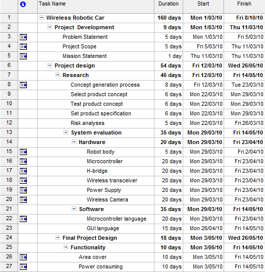
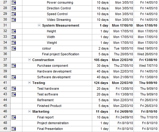
The following is the project’s calendar
Economic Analyses
Economic analysis for the project purposely establishes the product efficacy and its positive cost effective contribution to the society. The article “economic analysis” describes economic analysis as planned approach to optimize limited resources while opting for a cost-effective alternative. Economics is embodied in the concept of using less input resources for more output (optimizing) as well as minimizing resource wastage while targeting to achieve set goals. For instance, factor four and factor ten. However, these concepts have more meaning in the manufacturing arenas than in the mainstream economic field. An economic analysis of the project reveals that among other things the project guarantees human safety even though the economic costs associated with it are high [3]. Assembling the high- end technology devices will not only involve huge capital outlay but also the technical expertise of coming with their intelligent PIC microcontroller calls for a lot of individual sacrifice. This is attested by even the time committed to theoretically design functional frameworks as well as execute them to success. The need to undertake the market surveys in search project components that properly suit the functions better is a painstaking process but the project proponents have no alternative but to endure. However, the prototype tests on the breadboard rather than the PCB board aid cut costs as the latter is ordered tailor made from the manufacturer and in this case, the cost may go up. Human life is invaluable and precious and for that cannot be forgone. The increasing policy formulations to safeguard life sanctity while at the workplace through occupational health and safety regulations reflect the value addition of this project undertaking. Actually, these are core in the labor laws. Risks and damages incurred are high when human life is deployed in the danger zone. So do the employment rates of payment for the services delivered. The lifeless robotic cars can help cut costs and perform the risky duties in place human power. The application can additionally find its use in landmine areas, sites with radioactive activities, fire fighting and in spy missions. Some of the robotic car applications attest the imperative role during disaster preparedness and management. This may include the rapid response deployment in disaster scenes.
System Functionality
Design of the system is in such a way that makes it simple and ideal at the same time. Having a design with these properties makes the testing task comprehensive and debugging a lot easier. The system is comprises of smaller sub systems called modules. The modules are the mechanical body of the robot car, power supply, microcontroller, RF transceiver, camera, graphical user interface (GUI).
Mechanical body
The mechanical outfit of the car comprises of an off the shelf electric car – that is a motor and a set of wheels- and a camera mounted on top of it. PIC microcontroller controls the motor in the car.
The Power Supply
The system is mainly powered by a battery this is to avoid the use cables that may cause intertwining and ultimately cause failures. However, the power supply of the system does allow for external power connections that might be needed to carry out tests or other essential tasks [4].
PIC Microcontroller
The PIC microcontroller and specifically its 16f877a model is the control method of choice for this project. According to the article “PIC Microcontroller”, PIC stands for Programmable Interface Controls and among these controls is the microcontroller (2010). A PIC Microcontroller is preferred to other control methods as it facilitates communication in a system and control of the system. Take the 16f877 PIC microcontroller for instance; it comes with two Pulse Width Modulator Units that enable control of a system and two types of standard communication protocols that ensure greater communication within the system. Additionally, a PIC microcontroller provides a powerful platform on which to develop a program that controls the system and that provides greater video capabilities for the graphical user interface (GUI). The main functions to be controlled include; the speed and rotating angle of the front wheels, the movement direction of the robot that is forward or backward, the front and switching off and on of the backlights in case needed as supporting lights for the camera [13].
Wireless Transceiver
According to the article “Transceiver”, a transceiver doubles as a device that receives and transmits signals [19]. Considering that the system employs a 16f877 PIC microcontroller then the transceiver module must be compatible with either RS232 or SPI communication protocols. According to the article “RS-232”, RS-232 stands for Recommended Standard 232 (2010). The ER400 wireless transceiver chip manufactured by the LPRS Company is the transceiver model of choice for this project for a number of reasons. First, it is relatively cheap compared to other transceivers in the market. Secondly, it works on the RS232 protocol and thus it is fully compatible with the PIC microcontroller. Thirdly, its frequency of 433 MHz is suitable as it eliminates any chance of signal interference between it and the camera given that the camera functions with a frequency of 2.4 GHz. Finally, it comes with other inbuilt features that favor it for this project. These features include; built in crystal controlled synthesizer for frequency accuracy, 10mW Transmit RF power output, -105dBm sensitivity, serial input and output for transparent data transmission, low operating voltage i.e. 3.6 V, very low power consumption i.e. less than 23mA in transmit mode and less than 17mA in receiver mode and finally it is programmable [18].
There is a variety of transceivers that can be used with the RS-232 protocol that also give an output logic of 5V TTL or 3.3V TTL. The problem of these transceivers as far as this project is concerned is that apart from being expensive they operate at the same frequency as the camera used in this application. This clearly makes the system vulnerable to signal interference.
RS-232
The recommended standard 232 (RS -232) is a telecommunication standard that is applicable where single binary-ended data and control signals are in use. This standard is evident in Data Terminal Equipment (DTE) and Data Circuit Terminating Equipment (DCE) because these equipments incorporate single binary-ended data and control signals in their functionality. In computing this standard is effected through serial ports, which link, different devices so as to enable them communicate in a serial fashion.
The standard differentiates between a logical one and logical zero activities through setting distinct levels of data transmission and signal lines for the two activities. The standard works with signals with a voltage levels of ±3, ±5 V, ±10 V, ±12 V, and ±15 and specifies a maximum value of 25 volts when in use in a open – circuit. The standard further considers signals with a voltage value in the neighborhood of zero as invalid making communication via such signals null. These levels are common in computer-to-computer communication or between a computer and another device. Microcontrollers cannot output signals with such voltage ratings thus it is impeccable that an RS232 logic translator is fitted in the system between the microcontroller and the computer. The RS232 logic translator converts TTL levels from the computer to standard +/- 12 V levels that are suitable for microcontrollers and the reverse is also true. However, when communication is between microcontrollers, translation services – e.g. from a RS232 logic translator – are not needed as the microcontrollers transmit data with the same levels of voltage thus in such a case a straight connection is all that is needed. If a given driver or receiver complies with the RS232 standard then it means that the device can withstand a short circuit to ground or any voltage magnitude between zero and 25 volts.
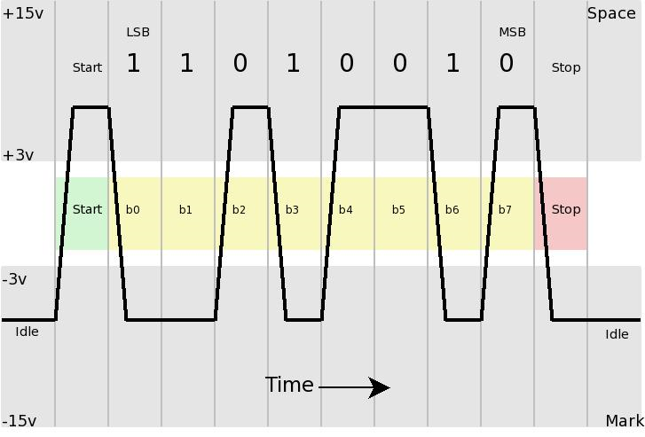
In an RS-232 circuitry with data transmission lines, a negative value of voltage indicates logic one activity, which implies that signals are in a state known as marking whereas a positive value of voltage indicates logic zero activity implying a signal state referred to as spacing. Logical inverting of control signals is done depending on what is seen in the data transmission lines. To illustrate if the voltage applied through the transmission line is between +3 and +15 volts then the signal is in active state however, if the voltage applied through the transmission line is between -3 and -15 volts then the signal is inactive state.
However, when communication is between microcontrollers, translation services – e.g. from a RS232 logic translator – are not needed as the microcontrollers transmit data with the same levels of voltage thus in such a case a straight connection is all that is needed [12].
The system will in its working transmit data in a serial fashion in packages of 8 bits each. The start and finish of each package is a solitary standard bit. The figure below further illustrates this concept
Graphical User Interface for the Robot
The article on Linux Project Information defines graphical User Interface as an application that enhances interaction between computer and human beings (2010).The graphical user interface should contain features for communication, video streaming and controlling the robot’s movements. The graphical user interface module will within contain sub modules, which are open serial port module, view camera module and sending movement control module. T o develop code for the open serial port module the services of the Microsoft Developer Network will be employed. A sample code will be taken based on the features of the serial port and then tested in a different but similar context (e.g. in a circuit that turns lights off and on) to determine if it works. If it works, adopt it into the project and work can begin on the next module. Developing a view camera module to appear on a PC-window will be done using the new filter graph system that has been introduced by Microsoft Corporation. This filter are custom made to assist video, sound and 3D developers through allowing easier and flexible construction of views used in programs and interfaces such as this. The movement control module’s interface will allow any user to control the robot. The interface is based on a circle hat is divided into six sections; each section has a name and a distinct color from the other. The names are to help a user identify and differentiate among the functions whereas the color will enable the program to identify the function of each sector, that is, each color corresponds to a specific movement. For instance, using figure 3 below, if the program identifies the color to be blue then the robot car will move forward and so on [20].
Wireless Camera
The appropriate camera for this project has to have a wireless capability, have a CCD sensor, night vision capability and use batteries as its source of power. Cameras with such features are available on eBay. Additionally, the camera should broadcast its video at a frequency of 2.4 GHz to eliminate chances of interference with signals transmitted at 433 MHz from the ER400 transceiver.
System Control
Controlling DC Motors
DC motor control is achievable through an H –bridge. To increase the speed of a DC motor you apply a lot of current through and to reverse its direction you change its polarity. An H-bridge through control logic changes the direction of the motor and through pulse; modulation varies the speed of the motor.
Directional Control
To get a motor to run in a desired direction you have to ensure that its two inputs are reverse of each other in the correct manner. To stop or halt the motor you have to ensure that there is a high or low signal at the two inputs of the DC motor. The truth table below illustrates cases for incorporation in the PIC microcontroller as a program.
Table1. Truth table for a bidirectional DC motor control
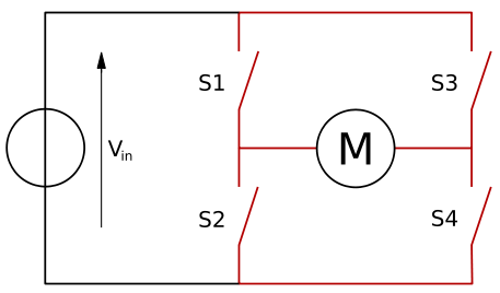
In order to control the angle of tilt of the motor its two pins are floated over between four switches by the H-bridge as shown in figure 4 above. The switches used for this purpose specifically contain either MOSFET or BJ transistors. According to the articles” Transistors and MOSFETS”, MOSFET stands for Metal Oxide Semiconductor Field Effect Transistor [11]. BJ stands for bipolar junction. Opening two of these transistor switches to power and the ground causes current to flow in one direction; ultimately the motor to rotate in one direction. To have the motor rotate in the reverse direction you close the already open switches and open the other two, one to power and the other to ground [1]
Speed Control
The speed of the motor is varied through pulses or signals sent to the motor by a Pulse Width Modulation (PWM) peripheral circuit. A PWM circuit according to the article “Pulse Width Modulation” is an efficient way of providing intermediate amounts of electrical power (2010). In PWM a circuit, the amount of voltage applied in the circuit is directly proportional to the width of the pulse generated. Furthermore, the speed of the motor is dependent on the width of the pulse generated, that is, the wider the pulse is the higher the speed of the motor and vice versa. So in order for the speed of the motor to be varied you have to vary the voltage applied on the circuit which will in turn vary the width of the pulse and which eventually varies the speed of the motor. Duty cycle is the ratio of the pulse width to the pulse length; it has been shown that at duty cycle of 100% the motor is at full speed, at 50 % duty cycle the motor is at half speed and at 0% duty cycle, the motor has halted [15].
System Communication
According to the article “Prototype”, prototype models as a pre-product of the actual product [14].The prototypes of the project are developed on a breadboard in modules and thorough testing done on each of the modules to check whether it is functioning properly. According Hewes (2010) breadboards largely find their use in fabrication of temporary circuits. After this, a PCB will be developed and the whole system put together and a final test done on the whole system as a unit [7].
The system implementation process will have five stages in it; these stages include camera stage, transceiver stage, microcontroller stage, PCB stage and the graphical user stage. During the camera stage, the functionality of the wireless camera in different environments will be examined together with that of its software in order to integrate it to the system. The transceiver implementation stage will involve carrying out a test of the transceiver in between two computers before finally installing it between the system computer and microcontroller. The Microcontroller stage will involve the adoption of the already developed microcontroller code and checking whether the microcontroller functions as desired. At the PCB stage, a final PCB will be adopted and the functionality of the car as a whole tested. The graphical user stage will involve the installation of the already designed graphical user interface into the system computer to make controlling and viewing easy and possible.
To appropriately appraise a process or product along its strong points, weak points, and potential impediment areas or malfunction method, and to thwart problems prior to their taking place, it may be essential to apply a Failure Modes and Effects Analysis (FMEA). An FMEA present a methodical strategy of determining the questions: “How can the project process or product fail? What will be the adverse systemic effects in the wake of failure? What constitutes the preventive mechanisms to avert failure? While a Process FMEA and a Design FMEA diverge in the areas of evaluation, the criteria of achieving either are more or less the same. The FMEA protocols are imperative on either stage (that is, Design and process) of a project life. The sooner a desirable alteration in the existing designs and processes are discerned, the lower the expense of making such changes. Procedures of implementing FMEA are rather not intricate but require rational in the sequence of actions stack on while follow up events are documented.
Live Streaming
Working with the camera and its program, the Camera Viewer, reveals much functionality e.g. operation of four cameras simultaneously, motion detection as well as voice and video recording. Another important feature is night vision capability, when the camera goes in a dark place its senses and its LED lights automatically turn on and visibility made possible in the dark. According to article “light-emitting diode”, LED stands for Light Emitting Diode (2010) [9].
RF Communication
As pointed out above, the transceiver implementation stage will involve carrying out two tests. In order for the whole system to function properly, it follows that its modules have to be functioning properly in the desired manner and the interconnection between these modules has to be done properly. In view of this, two tests on the RF transceiver module and in particular, the RF transceiver are carried out. The first test is conducted with the RF transceiver situated between two computers and the final test is conducted with transceiver between the PIC microcontroller and the system computer. The figure below shows the RF transmitter circuit done on a breadboard to aid in carrying out the test.
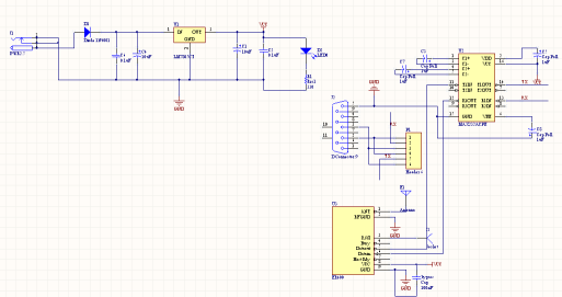
To carry out the first test, the above circuit will be connected between two computers with the aim of assessing the operation of the RF transistor in this context. The testing exercise is on a Windows platform as it relies solely on the services of the Window’s built-in Hyper Terminal program. The Windows Hyper Terminal program is available in all Window Operating Systems except Windows Vista and is an easy to use program. The process of setting up the transceiver’s port, for its use, will take into account the guidelines provided by the manufacturer of the RF transceiver chip. Considering the RF transceiver applicable for this project, the ER400 ,then the following configurations are appropriate for this particular test exercise; a standard data rate or baud rate of 9600 bps, 8 bits, 1 stop bit and no parity. This configuration will ensure easy and efficient data operations – sending and receiving data to be precise – by the Hyper Terminal program.
This setup does however present a problem. The problem is that the RF transceiver will be unable to transmit a continuous stream of data at the speed of normal typing. This problem arises from the fact that its maximum data transmission speed or baud rate is smaller in comparison with the speed of normal typing. This problem is however non-existent in the actual system due to the presence of a PIC microcontroller. Considering first, that the RF transceiver is unable to cope with the typing speed on a PC and that it is able to slow down the transmission speed of a PIC microcontroller. And secondly, that the PIC Microcontroller can cope with typing speed from the PC then its ideal design that the PIC microcontroller deals with the speed from the PC and that the RF transceiver deals with the PIC microcontroller at a speed it can handle.
Circuit Design
In circuit design, the final stage is coming up with a PCB. Considering that, the H-bridge and PWM dictate the speed and direction, there are dedicated RS232 serial pins and that the PIC controls the whole system except for the camera then the final design of the main control unit is as shown below
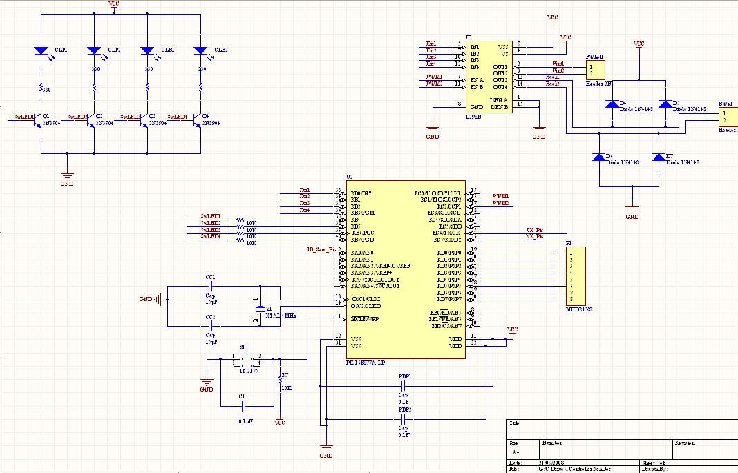
The controller unit design is such that it allows for flexibility, future improvements and/ or extra connections if needed. As the motor of the robot car runs, it is generating voltage, which in certain amounts can destroy the circuitry connecting to the motor e.g. the H – bridge circuit leading to the failure of the robot system as a whole. To prevent such failures of individual components and of the system at large precautions have to be taken. A fitting example of a precautionary measure undertaken is the adding and fitting of diodes on the driver’s side of the H – bridge to limit excess voltage. Such measures are important as they avoid unnecessary losses in resources and money. The use of diodes in performing such a function is not an invention of this project or a new idea in the making. It follows from knowledge already acquired in the electronics field. For example, the data sheet that comes with the L298 diode cheap recommends the use of diodes on the rails as the DC motor is driven.
At any given instance, the movement of the system’s motor can be in one of two directions (forward and reverse). The direction the motor movement takes is determined by the direction of flow of current in a circuit containing four transistor switches (MOSFET or BJ transistors). Diodes are not needed in the circuit that controls the movement direction of the motor because no risk is posed from excess voltage. This is because in controlling direction the motor does not run throughout and thus minimizes the generation of any voltage at all.
Light- emitting diodes (LEDs) are other components to be integrated into the system as shown in figure 6 above of the main controller unit. In this project, we have not determined the number of LEDs that will be required, also the strength of the LED has not been decide on and finally, the amount of current the LED would require to run in has also not been determined. Concerns do arise in light of these three queries. One such concern has to do with the flexibility of the circuit design as far as LED integration is concerned. To deal with this concern the system employs the use of transistors as switches that turn on the light-emitting diodes (LEDs) when it is desired. By opting to use such a method to control the light – emitting diode (s) the system becomes more flexible in the following way; that you can connect any type of light – emitting diode without worrying how much current it will use. Considering first, that the current to be supplied by the PIC microcontroller measures 25 mA in each pin. Secondly, that the current flowing through the transistors can go up to 1 A. Then, in order to carry out current limiting in the system a connection is done such that a set of resistors are in series connection with the light – emitting diode (LED). By carrying out such a connection, you accomplish two defining tasks. The first task completed is that the PIC microcontroller can supply voltage that turns on the transistor used in operating the light – emitting diode. The second task that is accomplished is that the transistor is enabled to handle the high current end of the circuit.
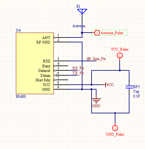
Wireless Transceiver
To incorporate the wireless transceiver chip as a part of the main controller unit the requirement is that you put a bypass capacitor as close as possible to the supply pins and having its antenna track at 0.3 mm. The diagram below shows the connection of the wireless transceiver chip:
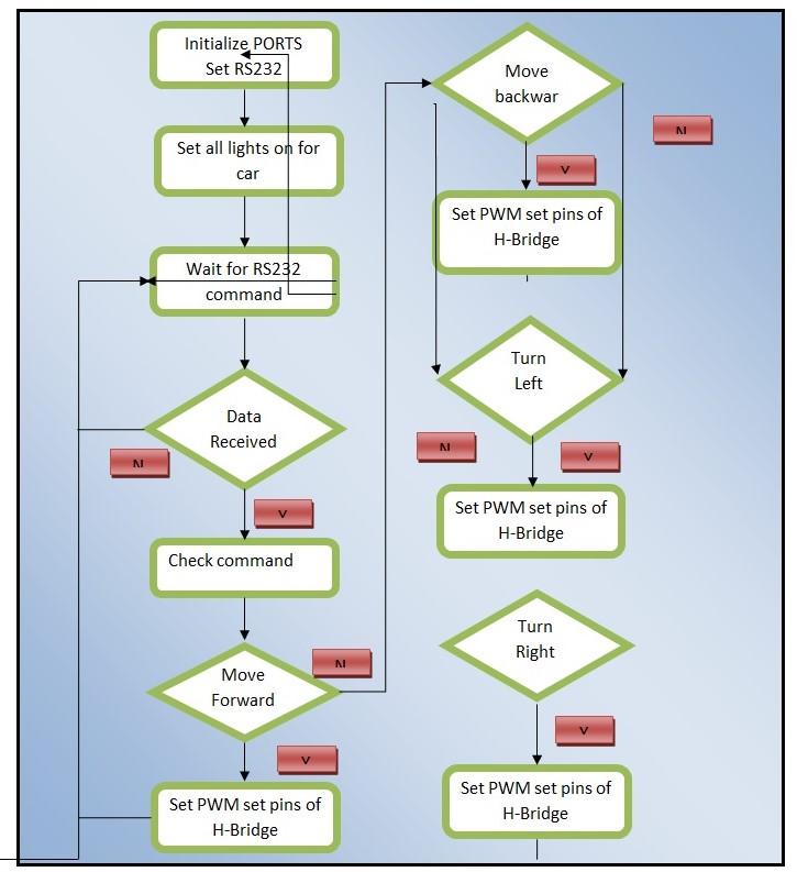
Programming the PIC microcontroller
The micro controller forms part of the hub for instruction communication, thus the programming stage of the PIC makes it imperative to have first to comprehend and factor its systemic input. This is due to the specific but multiple directional events expected for the wheel and lighting systems resulting from instructions communicated. The instructions should expectedly enhance the forward and reverse movements, to cause the wheel to turn on either side as well as automate switching of front and back lighting systems.
Project Activity Plan
The generation of theoretical designs and execution phase for this project unit spanned within one academic year period. An academic year consists of two semesters. Developing of the theoretical designs involved develop innovative ideas, conceptualizing and harmonizing the ideas, having the appropriate goals and objectives that will steer the project to its success, developing working frameworks and market exploration for compatible design components. In addition, rigorous screening and reconstituting of alternatives characterized the realizing of the final applicable conceptual design and its components thereof. The design phase formed major of bulk of the first semester while, execution phase was in the second semester. Theoretical frameworks involve examining both the existing and self-designed theories that will align themselves with the project objectives. While, theoretical frameworks are descriptive, conceptual frameworks are diagrammatic.
The initial task was to effect a functional relay between the PIC gadget and the computer. Prototype tests to ensure efficacy involved use of breadboard prior to executions. By programming the PIC, it relays a continuous traffic flow of letter “a”, when not functioning. According to the article “Program”, programming enables computer perform specified commands (2010). These commands are coded in line with the instructions for tasks that PIC microcontroller is to undertake. Slowing adjustments on the PIC traffic rate and re-powering resets it. Protel program was the platform for designing the system. The activity plan for executing and realizing the finalized project design in next semester will feature several tasks. The breadboard prototype will substituted for PCB board when executing the PIC microcontroller and PC relay system. The PCB board will be tailor made by the manufacture to suit project specifications. The C++ language will program PIC microcontroller. A graphical user interface on the PC will be custom-made to fast-track command response with the robotic gadget.
In computer science, graphical user interface provide short cuts to rather the elongated procedure of typing in commands. In most computer applications, graphical user interface are in form of icons that when prompted by a click a command is executed instantly. Graphical User Interface is considered as user friendly as it involves limited computer science technical expertise. The graphic user interface will run on Visual Basics program. The assembling stage will form the final bit of the project and realization of a fully functioning unit while in line with requirements. Piecing up different components provides the opportunity to vet and locate minor complications at their remote locations far much faster and avoids instances of complete overhaul of the system when searching for the complication when not spotted after full mounting.
Works Cited
- [1] “Bipolar Junction Transistor”. Anwers.com. 2010. Web.
- [2] “Charge-coupled device”. Anwers.com. 2010. Web.
- [3] Economic analysis.BusinessDictionary.com. 2010. Web.
- [4] “egonometrics”. usernomics. 2008. Web.
- [5] “GUI Definition”. The Linux Information Project. 2004. Web.
- [6] “H-bridge”. Answers.com. 2010. Web.
- [7] Hewes, J. “Breadboard” The Electronic Club. 2010. Web.
- [8] Huang H. PIC microcontroller: an introduction to software and hardware interfacing. New York: Cengage Learning, 2005.
- [9] “Light-emitting diode”. Anwers.com. 2010. Web.
- [10] Macmillan English Dictionary For Advanced Learners. Faye Carney, 2002.
- [11] “MOSFET”. Anwers.com. 2010. Web.
- [12] “PIC Microcontroller”. Answers.com. 2010. Web.
- [13] “Program”. TechTarget. 2010. Web.
- [14] “Prototype”. BusinessDictionary.com. 2010. Web.
- [15] “Pulse Width Modulation” Answers.com. 2010. Web.
- [16] “Radio Active Substances and Health”. Environmental Yellow pages Inc. 2010. Web.
- [17] “Robots”. AAAI. 2010. Web.
- [18] “RS-232”. Anwers.com. 2010. Web.
- [19] “Transceiver”. Anwers.com. 2010. Web.
- [20] Wilmshurst T. Designing embedded systems with PIC microcontrollers, principles and applications. London: Newnes, 2007.