Introduction
Various reasons are given in the planning and operation of a power system protection that involves overload protection devices such as over-current relays, differential relays, distance relays, circuit breakers, and other “special purpose overcurrent protective devices”.
These reasons can be summarised simply as to prevent power outage and major breakdown or blackout, and insure a 99.99% power supply. The devices are there to pre-empt overcurrent or overload, although on the outset, we can not totally prevent a short circuit. What we all want to accomplish is preventing blackout and ensure the safety of the devices and the connections.
In this new world of the digital age where enterprises fully rely on computers and the information technology, businesses need a 24-hour power supply with very minimal downtime. Businesses cannot afford an amount of power downtime; their computers are plugged in to connections all over the world and to what is happening around the globe; every bit and every second, any information that affects their business has to be checked out and entered into their databases. When a power outage occurs because of overload and overcurrent in a 24/7 power supply that can cause malfunctioning in relays, switches, fuses, and other electrical connections, a big amount of premium may get lost from the company in the process.
Curtis (2007) says: “Today more than ever, enterprises of all types and sizes are demanding 24-hour system availability. This means that enterprises must have a 24-hour power supply day after day, year after year” (1).
There is no place for a power outage in the digital age. Everything is wired; everyone is focused on his/her computer. An enterprise will spend a great amount of money to hire somebody or organization to produce this kind of power requirement with an almost zero downtime. For an electrical engineer, this is a big challenge that he faces in the fast-growing digital world.
By preventing an overcurrent and short circuit because of an almost perfect power supply protection and coordination, the electrical engineer delivers manifold objectives: preventing devices and other equipment from being damaged and insuring full power without interruption. This is the challenge the engineer or a team of electrical engineers has to face in power protection analysis and design.
As Jos Arrillaga (1990) says, “Ideally, power should be supplied without interruptions at constant frequency, constant voltage and with perfectly sinusoidal and, in the case of three-phase, symmetrical waveforms” (p. 1397). Symmetrical devices and hence symmetrical waveforms form part of a perfect protection and coordination.
Preface
Protection coordination is the major support, if not the lifeblood of a power supply, to say it bluntly, although the main lifeblood is the major power producer of any particular power connection.
Power system protection is very vital in the planning and operation of all power connections, be it a small or limited establishment or a large and multiple-connection enterprise, or even power involving a town or country, a transmission line or a substation. Analysis of power protection coordination is the main thrust of this paper.
Project Overview
The main scope of this study is power protection coordination and the various methods employed to protect a breakdown or power outage. We can narrow this down to a small room or a large building. The principle in a power protection coordination changes gradually as the power load increases or demand of more current changes. Power protection coordination means setting power amperages and wattages of components or parts, ampitages too, have to be coordinated with the connections. Changes in the connection include ratings of the devices, cables, and other interconnecting tools and equipment to ensure protection from overload and overcurrent.
There are numerous devices and power protection tools used and analysed in this study. Some of these devices and equipment have been proven effective in preventing short circuit and overcurrent. The devices include relays, circuit breakers, fuses, timers, and so on, and when they are discussed in the chapters ahead, their uses and how they work in circuits are shown. Mostly, we have consulted websites, catalogues, manuals, and other reading materials and information about these devices to be able to give a comprehensive analysis of their uses.
The main scope of this thesis is power protection analysis of a limited area. We can narrow this down to a small room or a large building; the principle is almost the same, in as much as we will be employing the same method – the application of relays, circuit breakers software by software, to insure power continuance and prevent breakdown and outages in a business establishment that needs 24/7 power supply.
A project can be started on power protection coordination and we can narrow this to a simple building which requires all the necessary connections for a full-time power supply. This simple building which can be up to several floors, serves as headquarters to a business enterprise that requires a 24/7 power supply.
What do we do?
All the necessary loads are given. We have to consider the circuit breakers, fuses, loads, and the ampacity of cables. The basement can be used as the monitoring room which the maintenance crew can concentrate on. There has to be a full-time monitoring/maintenance team, although this team can only be put on stand-by, but the one to monitor the activities, to watch the warnings and alarms may just be a single guard who can relay the warnings to the standby team.
Background and Literature Review
Background of Power System Protection
In this portion of the study, focus is on background and literature on power system protection and the devices used in implementing it. We will be dealing on relays, timers, circuit breakers, and fuses. They vary in form, size and internal make-up according to the amount of power and current needed, but the principle used as to their uses, the scope of coverage and the amount of current needed points to one direction – to protect the power system.
Power system protection involves pre-empting overload and over current. Overload is putting in series a certain component or electronic part or appliance above and over the capacity of the device – or should we say, the maximum tolerance of a particular instrument – which results in overcurrent. Short circuit is caused when a positive probe touches the ground, or when the positive terminal of a load is shorted to the ground. It is called a short because the two terminals or two opposite parts are attracted to each other. When this attraction becomes truly real, short circuit occurs. There will be overcurrent and some of the parts will break down. The circuit then will give different reactions. It’s like a domino effect, all interconnected parts and components will be affected. And this is the job of the designer of the protection coordination.
First, he has to prevent the short circuit. Then he also has to control the overcurrent. Nevertheless, this is the “invented” job of some high-tech devices which will be dealt with later on in this paper. There are devices that perform the job of protecting a short circuit in some connected devices, and then control the overcurrent. If this is a reality now, then what is the job of the electrical engineer. There are still many things to do. But more on this will be taken down in the preceding chapters.
Moreover, there are common causes of short circuit, and they can be avoided if steps and safety measures are followed.
Massimo Mitolo, Ph. D., and electrical engineer, says, “All electrical systems are susceptible to short circuits and the abnormal current levels they create. These currents can produce considerable thermal and mechanical stresses in electrical distribution equipment.” (Mitolo 2004)
National Electrical Code (NEC) (quoted in Brittian) defines overcurrent as “any current in excess of the rated current of the equipment or the ampacity of a conductor.” This happens when you put more devices or equipment over the required ampacity or more load to your connections. When this is done, more changes have to be instituted on the relays and other protective devices. Ratings now are in question when you add more loads.
Brittian further says that some of the causes of overcurrent are due to “defective conductor insulation, defective equipment, or an excessive workload burden placed upon the utilization equipment and its electrical circuit”.
The causes mentioned by Brittian are self-explanatory. But it has to be pointed out that overcurrent happens when there’s not enough current to support the load. Some calculations are in order for this dilemma.
Moreover, a load can be a device, an electronic part, transformer, or any electrical or electronic equipment that is added or connected to an electrical circuit or connection or device, which produces a change in the current consumption. A load adds extra current to a particular connection so that it has to be designed and the setting should be coordinated with the interconnecting devices in the circuit so that there’ll be no overload. The change in the current consumption has got to be coordinated so as not to produce an overload or malfunction in the circuit or connection.
So, here we can summarise the interconnection of terms. Overload means there is more than the required load of current in a given device or connection, and if this is not corrected by a protective device, there will surely be an overcurrent.
Additionally, a fault occurs when a wire, which has the “common” (in a dc power supply, this is the positive connection) connection makes “contact with an electrically conductive-grounded object, a ground fault is created” (Brittian 2002). This fault maybe caused by some loose connections or poorly insulated wires which make contact with the ground.
Relays
Relays have great significance in current protection and have been in use even before the advent of the so-called solid state devices, and software designed relays and fuses. Like any other device and equipment in the modern world, they have been modified and improved but the principle, uses and objectives are quite the same.
Keljik (2006) says:
“Relays are devices used to relay or multiply control signals or electrical contact closures. The relay concept is used where a small voltage at low current operates a set of electrical contacts to an open or closed position. This contact operation in turn controls a larger electric load and so on as it relays the electrical operations” (97).
Relays are used to control various loads from other electrical circuits. They may be used to operate large values of DC or AC power or simply the electrical circuit function.
With the emergence of the Information Technology, computers, fast information in the internet, various applications and modifications have been introduced on relays. Software applications too have modified the usage of relays; they have become very useful in safeguarding power connections and in detecting and warning overcurrent.
Khan et. al., state, “Protection relays have gone through major changes, from electromechanical to static and now to microprocessor-based multifunction programmable units” (253).
This refers to relays that are electronically made and are being aided with a software for its effective use.
Khan et. al., further reveal:
“The development of multifunction programmable relays has changed the protection philosophy for many industrial power systems. Many features, including metering, event logging, and additional protective elements, are available in the same unit, and, because the main cost is in the hardware and common input filtering, these features can be provided at a very reasonable cost” (253).
There is an upsurge of a variety of devices with high-tech applications to monitor overcurrent, and relays can’t escape this phenomenon. They are very useful as protective devices. Individual engineers and organizations have continued to modify and apply new ways to safeguard power connections because of the increasing need of a zero downtime in power supplies of industries.
Kinds of Relays
Thermal overload relay – this is used in used to detect overcurrent in motors. (Department of the Navy, 1991)
Thermal relays are used on motor connections. Motor protectors are important especially those that require DC current. This kind of relay is “responsive to ambient temperature” which means that if the temperature of a particular place changes “trip current” also changes. (The Department of the Navy, p. 3-1)
In detecting short-circuited coils, Keljik says, “The field coils of alternators can be checked for impedance by applying a high-frequency low voltage to each coil and measuring the current. The current in the coils should be equal. The presence of a high current usually means that there are shorted turns somewhere in the coil” (324).
In relay coordination, there are required information and settings for connection and these are amperes rating which is in accordance with NFPA 70 regulations, time-current characteristic curves, ampere setting of the rotor and the ampere damage time for medium-voltage motors. (The Department of the Navy, p. 3-1)
In employing relays, it is necessary to determine first the ampere rating (as stated above, it should be in accordance with NFPA 70 to prevent overload. A study also has to be conducted with regard to the characteristic curves.
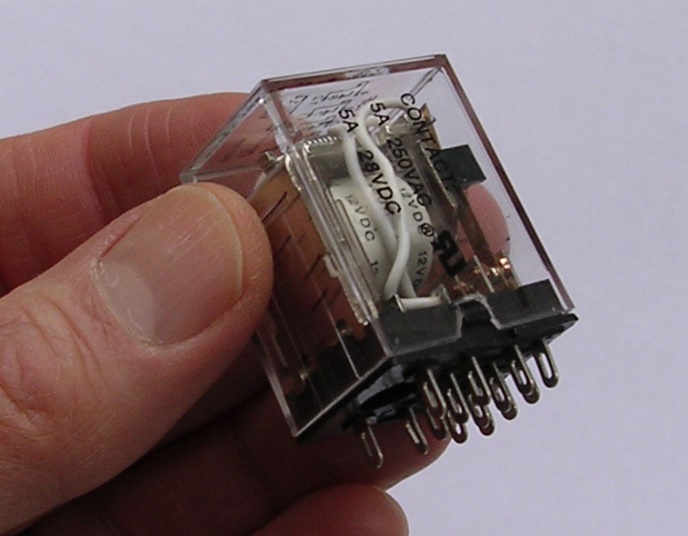
Relays vary in size, form, make and purpose, from a simple normally-open, or normally-close switch such as the time over-current relay shown:
With the introduction of sophisticated devices or equipment, overcurrent protection has become manageable, but the scope is multi-faceted. For example AREVA has introduced the MICOM concept with its “range of components, systems and services from AREVA T&D” (AREVA MiCOM P111 Overcurrent Relay Technical Manual 2006, p. 1-7/12).
Their product MiCOM is a complicated device but with many applications. The manual says:
“MiCOM is a comprehensive solution capable of meeting all electricity supply requirements.” It can integrate its communication capabilities with a power supply control system. Its components are defined as:
- “P range protection relays;
- “C range control products;
- “M range measurement products for accurate metering and monitoring;
- “S range versatile PC support and substation control packages.” (AREVA MiCOM, p. 1-7/12)
The manual further states:
“MiCOM products include extensive facilities for recording information on the state and behavior of the power system using disturbance and fault records. They can also provide measurements of the system at regular intervals to a control center enabling remote monitoring and control to take place” (p. 1-7/12).
This is another state-of-the-art product that can be used in a power supply with a 24-7 power requirement. This can be applied to a headquarters office for the needed protection design. Other software can be as effective, but this one has many features, too.
MiCOM P111 is composed of feeder protection relays which “are fully numerical in their design, implementing all protection and non-protection functions in software. The relays employ a high degree of self checking and, in the unlikely event of a failure, will give an alarm. As a result of this, the commissioning tests do not need to be as extensive as with non-numeric electronic or electro-mechanical relays.” (AREVA MiCOM Manual, p. 10-3/26)
Modern relays are equipped with multiple output relays. In this example product, the MiCOM is equipped with an alarm, and can protect an advancing over-current by detecting an incoming short circuit. It acts as a guard and doctor at the same time. In the United States where the three-phase system is used, complicated relays with multiple purposes are being introduced by various manufacturers to insure reliability in case of overcurrent by inputted equipment or connections. Coordination still is relevant. It is still required even in the presence of sophisticated and reliable overcurrent protectors.
Another example of a complicated relay is this one by ABB – the Three-phase Overcurrent Relay SPAJ 131C which is a sophisticated multi-featured overcurrent relay that has:
- “three-phase low-set phase overcurrent stage with definite time or inverse time characteristic,
- “High-set phase overcurrent stage with definite time characteristic,
- “Can also be used for single-phase, two-phase or three-phase overcurrent protection,
- “Both overcurrent stages can be blocked by an external control signal, and
- “Output relay functions freely configurable for the desired operation, among others” (ABB Manual 1999, p. 3).
This kind of overcurrent relay is designed “to be used for two-stage phase overcurrent protection of distribution feeders, large low-voltage motors, high-voltage motors, medium-sized and large generators and power transformers” (p. 3).
However, this is used as a secondary relay connected to the current transformers of a connection or object being protected. The significance of this kind of relay is that “on the occurrence of a fault the overcurrent relay generates an alarm signal, trips the circuit breaker or starts external auto-reclose functions, in accordance with the current application” (p. 3)
In the project of a building and compound, we can also use this as an alternative.
Protective relays
Other examples of relays that we can use in particular uses are protective relays.
“Protective relays are classified according to their function, and there are a wide variety of protective relays available” (The Department of the Navy, p. 3-9).
A desired value of current can be preset, and there is an overcurrent, this kind of relay detects and “reacts” in the process.
Differential Relays
Differential relays are employed for fast tripping and faults protection. One example is the SEL-587Z Relay, a single zone bus protection. It is described as “Bus or Transformer High-Impedance Differential Relay”.
Schweitzer Engineering Laboratories which own promotes this kind of high-technology device say that this is a high-impedance different relay with fast tripping, designed for a three-phase protection and cost effective.
A “bus” can be found in a transmission or distribution system network. A transmission or distribution system network is “an assemblage of a linear, passive, bilateral network of impedances connected in a certain manner. The points of connections of these elements are described as buses or nodes” (Das 2002, p. 72).
We can find several of these nodes and “buses” in the project of a building and compound of residential houses. Connections can be done by a team of engineers and linemen, but in actual project, a few of these linemen can act as the standby team. There’s not much manpower needed most of the time.
Distance Relays
The US Patent 6661630 is an example of a distance relay which is particularly used for transmission lines, and when this is connected it is capable of estimating impedance when faults or short circuits occur in a remote end of the connection. (US Patent 6661630).
This one again is operated by a software that can correct itself. Also, there are various distance relays manufactured by different manufacturers and with different designs. Usually, they are installed on transmission lines.
They are called distance relays because they are used to measure impedance at the remote end of a line. It bears its name, and the explanation is provided by GE Power Management:
“Distance functions perform a very important and essential part of many power system protective relaying systems. It is the responsibility of the manufacturer to design relays, and to aid in their application, with these problems in mind. However, it is the ultimate responsibility of the user to insure that the relays are applied correctly” (GE Power Management).
Another kind of Relay is the SSR or the Solid State Relay, a semi-conductor which “can be used to control most of the circuits that the electromechanical relay controls [and] has no coil or contacts; they are compact, versatile, and very reliable if used in the proper application” (Keljik, p. 98).
Circuit Breakers
The American National Standards Institute (ANSI) defines a circuit breaker as, “A mechanical switching device, capable of making, carrying and breaking currents under normal circuit conditions. Also capable of making and carrying for a specified time and breaking currents under specified abnormal circuit conditions, such as those of a short circuit” (Brittian 2002).
In the olden days of electricity, people used the electromechanical trip devices, but with the introduction of the solid-state devices, the electromechanical has been replaced. “Solid-state trips are more accessible, easier to calibrate, and are virtually unaffected by vibration, temperature, altitude, and duty-cycle” (The Department of the Navy, p. 3-3.
For the kinds of circuit breaker, we have:
- The low-voltage circuit breaker, which is “classified as molded-case circuit breaker or power circuit breaker” (The Department of the Navy, p. 3-3).
- “The inverse-time (or thermal-magnetic) circuit breaker [which] contains a thermal and a magnetic element in series and is similar in operation to time delay fuses” (The Department of the Navy, p. 3-6). This means that the circuit breaker responds to the heat produced, and the magnetic contacts react to the short circuit current.
- “The instantaneous-trip circuit breaker is nothing more than an inverse-time circuit breaker with the thermal element removed and is similar in operation to the non-time delay fuse” (The Department of the Navy, p. 3-6).
- Moulded Case Circuit Breaker – this kind of circuit breaker has “voltage rating, (AC/DC) current rating, and breaking capacity rating “ (Hewitson et. al., p. 158).
- Solid State Relay – According to Jeff Keljik, the Solid State Relay or SSR can be used to control most of the circuits that the electromechanical relay controls. “By comparison, the SSR has no coil or contacts. The semiconductor industry has developed solid-state components with unusual applications to the industrial control processes” (Keljik, p. 98)
Fuses – Fuses are also very common overcurrent protection. We can find this at home or in the office because they are used to protect equipment and power connections in cases of malfunctioning as a result of overcurrent.
“A fuse is a non-adjustable, direct acting, single-phase device that responds to both the magnitude and duration of current flo0wing through it.” (Department of the Navy 1991, p. 3-1)
Kinds of fuses:
- “Nontime delay fuses – consists of a single type of fusible element, called a short-circuit element.
- “Time delay fuses – constructed with two different types of fusible elements: overload and short-circuit.
- “UL Classification – classified as low-voltage fuses;
- “Time-current characteristic curves [these fuses have an operating band similar to a resistor, but they are classified for medium-, high- and low-voltages fuses]
- “Current-limitation – fast-acting that they are able to open the circuit and remove the short-circuit current well before it reaches peak value [and before affecting the next device]
- “Medium-voltage fuses – are either (1) distribution fuse cutouts or (2) power fuses. Distribution fuse cutouts are designed for pole or crossarm mounting and should be used primarily on distribution feeders and circuits.
- “High-voltage fuses – rated for outdoor use only,
- “Current-limiting power fuses” [various limiting current which open in different time intervals] (The Department of the Navy 1991, p. 3-2).
Timers
There are many kinds of timers. “Mechanical timers use either clock motors to operate a mechanical trip mechanism or solenoids to create timing operations” (Keljik, p. 103)
Other timers use air, a diaphragm, and a operating solenoid to cause a time delay. Keljik gives us examples of some types of timers, and they are:
- Pneumatic timers – used for on or off delay operation. With the solid state and semiconductor, we have transistors and ICs that produce this similar kind of work, the on and off delay. According to Keljik, “in the on-delay timers (time delay on energization) the contacts stay in their original position until a solenoid plunger has moved through its entire travel distance [and] the travel time is controlled by adjusting a needle valve to allow the air to escape in front of the solenoid diaphragm. The timer solenoid has power applied to pull the plunger into its timed-out position” (Keljik, p. 103).
- The off-delay timer – this is the time delay on deenergization, and “acts in the opposite mode.” In other words, the timing change to the contacts takes place when the power is removed from the timer coil and the solenoid plunge is allowed to go back to its deenergized position. (Keljik, p. 105)
Other causes of short circuit
Looking for short circuits is a form of trouble shooting. Motors and coils require some amount of skill in troubleshooting. Motors are loads and sometimes they work, though poorly, even if there’s something wrong inside the circuit. A circuit breaker can detect this, or a thermal fuse. When troubleshooting points to the motor as the culprit, some other troubleshooting techniques have to be done.
Disconnect right away the suspected motor, and replace it if there’s some replacement available. However, to be sure with your suspicions, some amount of troubleshooting skill is required.
Jeff Keljik gives us this troubleshooting method:
“Open-circuited coils on rotors or stators can be located by continuity (one end to the other) tests. Short-circuited coils are located easily by the use of a growler. A growler is an instrument consisting of an electromagnetic yoke and winding excited from an AC source. The yoke is placed across a section of slots containing the winding of a transformer, and the winding being tested acts as the secondary.”
This is the so-called “real” side of troubleshooting a motor. This method uses a tester that has an ammeter. The yoke which acts as the primary coil will be tested for the current, and when the current rises, it shows that the coil is short circuited. Prolonging the stay of the current in the coil will produce heat in the coil. Thermal testing then is done.
Keljik says, “The stator windings of both alternators and motors can be tested by this method” (Keljik p. 323).
Alternators can also be checked using the voltage-drop method described for DC machinery testing. The field-coils can be tested of its voltage.
‘With a given value of current in the field circuit, the voltage on individual field coils should be approximately equal. If a voltage-drop difference is in excess of 5 percent, the coil should be investigated for shorted turns. The presence of full line voltage across a single coil indicates an open circuit in that coil” (Keljik, p. 323)
Solid state timers are now in use instead of the traditional or old-time timers. Solid state timer is more accurate and requires small amount of current and voltage to operate. According to Keljik, “Many of the timers can be used as on-delays or off-delays and have several trigger modes. They can also provide a wide range of timing, from milliseconds to hundreds of hours. The timing is accomplished with electronics, which makes them accurate and precise.”
On the other hand, these solid state timers are incorporated into some of those mentioned relays in the early part of this paper. They are run by software and software can only control solid state or semiconductor devices. These solid state components are ICs inside the relays and breakers.
Load Flow and Short Circuit calculations
This chapter will answer the following questions:
- What are load calculations and their formulas used in this project?
- What are short circuit calculations?
- What is over-current?
Short circuit calculations are carried out by using “an analysis method called symmetrical components … based on the principle that any unbalanced set of vectors can be represented by a set of three balanced quantities, namely: positive, negative and zero sequence vectors” (Hewitson et. al., p. 11)
The formulae to be carried out and used in this study are:
- “Ohm’s Law – unit of measurement is in Ohms or the sign Ω.
- “Percentage impedance methods: The impedances are expressed in percentage with respect to a base MVA.
- Per unit method: Is similar to the percentage impedance method except that the percentages are converted to equivalent decimals and again expressed to a common base MVA” (Hewitson et. al., p. 19).
Ohm’s Law is stated in the formula E (V) = IR, where E = Voltage, I for Current and R for Resistance. In layman’s terms, this is expressed as: Voltage is directly proportional to the current and the resistance. This is applicable to dc current output of a power supply.
Where we have:
- “P = Power in watts
- “I = Intensity of current in amperes
- “R = Resistance in ohms
- “E = Electromotive force in volts” (Keljik, p. x)
The Ohm’s Law is a common formula used in electronics and electricity. This s used in solving the unknown values of the three forces involved in a circuit: power, resistance and voltage. When the voltage is unknown but the power and resistance values are known, we can get the value of the voltage. Likewise, both the power and the resistance can be solved using two of the known forces.
This can be used in circuit analysis, or when there is a short circuit. If one exceeds after using the formula, the tested values of the components and the circuit voltages and power can give a comparison, thereby pointing out that there is a fault or short circuit in the power in question.
For AC systems, we have Voltage = IZ, where Z is Impedance, and expressed this way: Voltage is directly proportional to Current and Impedance. Or, Current is directly proportional to the Voltage and inversely proportional to the Current.
Impedance is “the AC equivalent of resistance in a DC system and takes into account the additional effects of reactance [and] represented by the symbol Z” (Hewitt et al, p. 12).
This is calculated by the formula: ”Z = R + jX, where R is the resistance and X is the reactance.” (p. 12)
Reactance is the result brought about by the inductance and capacitance effects of the system. “Energy is required to overcome these components as they react to the source and effectively reduce the useful power available to a system.” (Hewitson et al., p. 13)
We can solve the reactance with the formula:
“Inductive reactance = 2 ¶ f L” (p. 13)
“Capacitance is the electrostatic charge required when energizing the system. It is represented by the symbol C and is measured in farads.” (Hewitson, p. 13)
This is the unit of measurement of a capacitor which stores electrical charges in electric circuits. The formula:
“Capacitive reactance = 1 2 ¶ f C “ (p. 13)
Where:
- f = supply frequency,
- L = system inductance and C = system capacitance” (p. 13)
On the other hand, another useful tool in electrical engineering is analyzing vectors. “Vectors are instantaneous ‘snapshots’ of an AC sinusoidal wave, represented by a straight line and a direction.
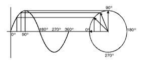
Hewitt et al. state:
“For a typical sine wave, the vector line will be horizontal at 0° of the reference point and will be vertical upwards at 90° and … comes back to the horizontal position at 360° or at the start of the next cycle (Hewitson et al., p. 12)
Equations to calculate overload.
![]()
We usually use Kirchoff’s laws in calculating fault equations.
- “3-phase fault:
- “phase-phase fault:

- “phase-earth fault:
From the equations above, we have this data:
- “Z = Impedance per phase, Ω
- “Z0 = Earth return impedance, Ω
- “VLN = Line to neutral voltage” (My Electrical Wiki, 2009).
With reference to calculations, Mitolo cites NEC provision which says:
“’Equipment intended to interrupt current at fault levels shall have an interrupting rating sufficient for the nominal circuit voltage and the current that is available at the line terminals of the equipment.’” (NEC Provision cited in Mitolo 2004)
The ANSI/IEEE state that in calculating short circuits, it is “assumed that the fault impedance is zero and the pre-fault voltage is constant during the evolution of the fault” (cited in Mitolo 2004). However, Mitolo further argues that in actuality, “the fault has its own impedance, and the voltage drop, due to the short-circuit current, lowers the driving voltage.”
Calculating the Thevenin theory which states the equivalent impedance during the time of the fault is the classical approach of calculating short circuits.
The figure below is Dr. Mitolo’s example of a simplified power distribution system with corresponding values:
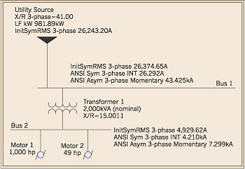
Calculations
We have to convert the impedances into per unit values. For example, we can use this formula, as mentioned by Mitolo, as follows:
- Sbase = 100MVA
- Vbase = 26.4 kV
Mitolo arrived at a formula which is:
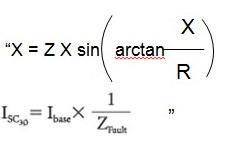
The calculations follow the step-by-step process specified by ANSI/IEEE procedure, described in IEEE Std. C37.010-1979, which is used for high-voltage or 100V equipment.
The Thevenin impedance is arrived at here by combining “the per unit X and R values”.
“ZFault=(Zutility+ZT1)||ZMotor1||ZMotor2=(0.0021+j0.083+0.005+j0.07)||(0.49+j13.8)||(29.8+j298
=0.166+j2.817 pu=2.823ej86.6”
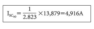
The short circuit current rms in the example Bus 2 is: “ “
In a project of a building with offices and a compound of small residential buildings for its employees, calculations can be narrowed down to the building, and the residential area.
In this project, the software ETAP can determine the specifications that can be applied on the building and the residential area.
Background Theory on the Power System Protection Coordination
This part of the study deals with the theory on power system protection coordination. As man progresses in every field of endeavor, he employs factors to protect himself. This applies to every aspect of life and in the area of invention, for example technology, and at present the digital world. It is undeniable that there are thousands of lightning and thunderstorms that occur every second, every minute all over the earth. It is said that the earth is a big magnetic field and also a big source of electricity. When lightning strikes, it is a big hazard for man and his inventions, to include properties and animals. With this, he has tried every means to employ protection devices, from crude lightning rods to complicated lightning arresters.
Electricity is one of the best inventions of man but which require extra care and attention because reluctance and irresponsibility on his part mean loss of lives and property and a great part of all his efforts and accomplishments.
Like the subject of protection coordination – this is a job that demands great amount of knowledge, expertise, experience, and effort and skill. You can never tell that the job is finished if it seems all things are already in place, or that you have done all you are supposed to do, so the job is finished. No! Checks and counter-checking, testing and watching and maintaining what you have done are what is expected of a responsible electrical engineer who will see to it that there will be no breakdown.
The theory of protection coordination lies on this. Protection involves knowing each and every part and component in a circuit.
Coordination is a must for a power system protection, if not there will be a downtime, or the system malfunctions. Input current has got to be coordinated with its output, or something gives up. The output must be considered as far as the input is concerned. Proper ratings for devices have got to be designed in accordance with specifications on devices and connections.
In power system protection, the basic theory is that the bigger the load or the inputted device, the bigger is the required device to carry the load. That’s simple logic, or mathematics.
Hewitson et. al., state:
“The basic theory of selective coordination is applicable for all values of electrical fault current.
- “Milli-amperes: Earth leakage protection
- “Hundreds of amperes: Overload protection
- “Thousands of amperes: Short circuit protection” (Hewitson et. al. p., 160).
This is quite simple to understand: you can’t connect a heavy of load hundreds of amperes to a milli-ampere relay or fuse or minimal ampitage. You’ll witness a destruction, or a big problem in the power system coordination. Everything has to have its own rating, from the devices an electrical engineer purchases to the connections. Every project which involves connections with lots of loads and devices have to follow rules. The ratings in all parts to be connected are prescribed properly by authorities and organisations to safeguard the lives and properties.
The word coordination itself is self-explanatory. Everything – every device, cable, tool, etc. – involved in the connection of the power supply, in line and acting as a load, from simple wires and cables, to switches, fuses, circuit breakers, timers – they have to be coordinated to avoid overcurrent, overload, and malfunction.
A coordination study should be instituted by the electrical engineer, or any department for the matter, when new equipment is introduced or when a new device with a large load is reconnected into the system, or even when minor changes are being done in the system. This is the challenge of the electrical engineer – producing a power system protection coordination.
Protection coordination is one of the most important principles in electrical connection, in providing power supply to enterprises, establishments, and to any project that requires electrical connections. It’s important as troubleshooting or repairing or maintaining a power connection or supply.
“The primary purpose of the coordination procedure is to select the proper ratings and settings for the protective devices on an electrical distribution system” (The Department of the Navy, p. 4-6).
Coordination study is constantly changing and revised depending on the loads and devices connected. Once there are changes, breaker settings and fuses have to be changed or revised in their amperage and current requirements, and they have to be coordinated and balanced so that no fuse trips and circuit breakers malfunction as a result of overcurrent. Calculations too are in order along this area.
What are to be consulted are current ratings from manufacturers, rules and regulations from authoritative agencies, and most specifically, the original and the new diagrams and plans of the system to be affected. Coordination therefore is balancing, considering the input to arrive at the output, preventing and curing in the process to avoid malfunctions and power downtime.
The Department of the Navy states: “A new or revised coordination study should be made when the available short-circuit current from the power supply is increased; when new large loads are added or existing equipment is replaced with larger equipment; when a fault shuts down a large part of the system; or when protective devices are upgraded” (The Department of the Navy, p. 4-1).
There’s the big job that awaits the engineer once changes occur in the loads, and the devices and equipment. Once changes occur, there’s a continuing reaction along the lines and connections of the devices affected – circuit breakers and fuses might trip. In other words, a balancing of the loads, or the inputs and outputs has to be done once there are changes. “…[A] comparison is made of the operating times of all the devices in response to various levels of overcurrent” (p. 4-1).
The same document of the Department of the Navy provides a long list of data needed for the coordination study which includes:
- Single-line diagram of the system under study;
- System voltage levels;
- Income power supply data [this includes impedance and MVA data, X/R ratio, existing protection, including relay device numbers and settings, CT rations, and time-current characteristic curves, etc.]
- Data on system under study [transformer ratings, etc.)
- Short circuit and load current data” (The Department of the Navy, p. 4-1)
We can start a coordination procedure by “selecting a convenient voltage base and converting all ampere values to this common base.” Then, follow these procedures:
- “Indicate short-circuit currents on the horizontal axis of the log-log graph.
- “Indicate largest (or worst case) load ampaities on the horizontal axis;
- “Specify protection points. (Consider NFPA 70 limits for large transformers)
- “Indicate protective relay pick-up ranges.
- “Starting with the largest (or worst case) load at the lowest voltage level, plot the curve for this device on the extreme left side of the log-log graph.
- “Using the overlay principle, trace the curves for all protective devices on a composite graph, selecting ratings or settings that will provide over-current protection and ensure no overlapping of curves” (The Department of the Navy, p. 4-2).
When new equipment such as transformers are connected, knowledge of NFPA 70 transformer limits is a must. “NFPA 70 specifies the maximum overcurrent setting for transformer protective devices” (p. 4-6).
Earthing Device
Solid earthing
The neutral of a power transformer is earthed solidly with a copper conductor as shown in the sketch.
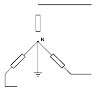
The advantages of a solid power transformer are stated by Hewitson et. al.:
- “Neutral held effectively at earth potential.
- “Phase-to-ground faults of same magnitude as phase-to-phase faults; so no need for special sensitive relays.
- “Cost of current limiting device is eliminated.
- “Grading insulation towards neutral point N reduces size and cost of transformers” (Hewitson et. al., p. 27).
Background Information on ETAP Software

ETAP logo bears the phrase “thinking power”. Given the short time in reading and analysing its website, this paper can give an A+ grade for ETAP makers and programmers. It truly has a thinking power – the features are good, and the software that incorporates all the features and coordinated to deliver a safe and reliable power supply seems very workable for this digital world.
This is the power design analysis and application fit for the high-tech world – the digital age where software solutions are incorporated into a power distribution and transmission, minimizing manpower, labor costs, and troubleshooting time, and delivering effective and safe power with very minimal faults that can result to overcurrent and power downtime. In the opinion of this study, this is one of the best solutions for reducing power downtime and ensuring enterprises with 99.99% power 24/7. ETAP features and designs follow.
ETAP is summarized in a single phrase “Enterprise Solution for Electrical Power Systems”.
In its website, it formulates a well-defined literature capable of enticing would-be buyers. It has a wide array of products and services capable of protecting and maintaining electrical installations and power supplies to homes and large organizations.
“ETAP is the most comprehensive analysis platform for the design, simulation, operation, control, optimization, and automation of generation, transmission, distribution, and industrial power systems” (ETAP website).
ETAP employs a wide range of software solutions which are integrated, and this includes: “arc flash, load flow, short circuit, relay coordination, cable ampacity, transient stability, optimal power flow, and more” (ETAP website).
Powerful features for ETAP include:
- “PS or Power System Simulator
- “STAR or Device Coordination & Selectivity – This has AC & DC coordination, applicable to appliances that require DC power supply; graphically adjustable device settings, multi-function/level relays, among others.
- “ARTTS or Advanced Relay Testing & Transient Simulator. The Relay Test Set Equipment is quite state-of-the-art, just like the rest of their devices. The equipment “test, simulate, & calibrate relays, meters, & transducers” and supported by a Relay Test Set Software.
- “PSMS or Power System Monitoring & Simulation – This is the equivalent to a “war room” or monitoring station where there is a “multi-console with multi-screen monitoring, graphical monitoring via one-line diagram, alarm annunciation with graphical interface, and OPC interface layer” (ETAP Overview, p. 3)
- “EMS or Energy Management System – features automatic general control, demand side management, and supervisory control that includes autocontrol overload, undervoltage, and so on. (ETAP Overview, p. 2)
- “ILS or Intelligent Load Shedding – with optimal load shedding and load preservation” (ETAP website).
These six features or tools constitute ETAP software that truly revolutionize design and analysis tools for power systems.
ETAP employs the network analysis devices to include: Short-Circuit ANSI which corresponds with ANSI/IEEE C37 Standards; Short-Circuit IEC Standards, Arc Flash, Load flow. ETAP also delivers power quality which is characterised by “harmonic load flow (IEEE 519 Standard), frequency scan, and harmonic filters” (ETAP Overview, p. 3).
ETAP software is applicable on a building with offices, and a compound about 2 hectares in size and with a small population occupying small residential buildings. Transmission lines and cables have to be installed. The different offices are also to be installed with breakers and switches.
More so, ETAP can do this with some amount of accuracy.
ETAP has a monitoring room for viewing and guarding the necessary circuit problems and overcurrent occurrences, malfunctions, and overloads. The many features of this project with ETAP is a good model for electrical engineers to observe and take note because this will not only be sample but could be something to be thought about and a reality someday.
One other important feature of ETAP is its parameter on Cable Systems (see image).

The features for the Cable Systems make it clear that their products are of quality and can withstand rough weather and time. They have the “Underground Thermal Analysis” with these characteristics: “Neher-McGrath method, IEC 60287 method, steady-state temperature, ampacity optimization, and automatic cable sizing” (ETAP Overview, p. 2).
They also have “Cable Pulling”, characterised by: “3-D isometric view, pull multiple cables, forward & reverse tension, sidewall pressure, pull different size cables, vertical & horizontal levels, and checks for NEC requirements” (ETAP overview, p. 2).
Among ETAP’s other features are the “Ground Grid Systems” characterised by “Finite Element Method” and “IEEE 80 & 665 Methods”.
ETAP’s transformer is done with MVA sizing which is “based on actual connected or operating load, includes ANSI and IEC standard types, classes, & ratings, and considers ambient temperature, altitude, growth, & load factors, et.” (ETAP Overview, p. 3).
Another remarkable feature of ETAP is its Intelligent load shedding which has these characteristics:
- “Response to mechanical & electrical disturbances
- “User-definable control logics & macros
- “Operator friendly interface
- “Unlimited load shedding schedules
- “Fast response time, and
- “Reliable Operation” (ETAP Overview, p. 3).
The EMS or Energy Management System has “automatic generation control, demand side management, and supervisory control” which means that many of the features are automatic and respond by itself, requiring less manpower.
Conclusion (Protection Coordination Thesis)
Protection Coordination is a preventive and curative process in a power supply. The design has got to follow rules, specifications, ratings, and other requirements from the government of a particular country and from the manufacturer of the various devices because they themselves follow the rules and the mandated specifications in their products.
In designing a protection coordination for an enterprise, a building, or that which requires a larger area, there are many things to be considered.
The application of a software can be a big help and tool for the coordination. ETAP in this sense is recommended, but in the unlikely event that this is not possible, there are many other circuit breakers and relays that can be used with more precise work, load and functions.
After the decision has been done on the software, the other moves involve the proper installations in the design. The plan map has to be followed with the specified cables, devices, tools, circuit breakers, and fuses, installed properly. All specifications and rules have to be followed, and these are in the blue-print.
Coordination needs time with the right people and a team to carry out the objectives of the project. When all things have been considered, that’s the time work is done with speed and accuracy. When all things are in place, a follow-through of all the connections have to be tested, and maintained, now applying the practical sides.
In this project, theoretical and practical applications were given consideration on the different connections of a power supply, especially the significant devices that can be used. The devices and other particular brands were cited and studied as to their applicability in the power system protection coordination.
As mentioned in the Introduction of this study, the electrical engineer has to anticipate an overcurrent and short circuit in order to prevent damage and insure full power without interruption. However, there are always short circuits. This is not to say that the process or the work of the engineer is weak or at fault itself.
There are many causes of short circuits that result into overcurrent. Loose connections, poor insulation, overload, and so on, are among the few mentioned and it is the challenge of the electrical engineer to make the right moves, the right connections, and the exact planning and design, so that any untoward incident that may occur, the fault is addressed right away.
In the “headquarters project”, monitoring activities can be focused on the ETAP which itself will do the monitoring.
The loads are carefully watched round the clock with the aid of the ETAP software. Breakers and fuses can also watch an over current, however, this can be easily detected by the warning device of the software.
We have considered the ampacity of cables and the connections. The basement can be used as the monitoring room which the maintenance crew can concentrate on. A 24-hour monitoring/maintenance team can be on the watch, although this team can only be put on stand-by, but the one to monitor the activities, to watch the warnings and alarms may just be a single guard who can relay the warnings to the standby team.
Recommendations and Future Work
This chapter will deal on recommendations and future work to improve protection coordination in industrial establishments as well as buildings that require 24/7 full-time power supply.
Power Coordination in any electrical project should be a part of the planning stage. We think this is a must, and is part of the preparations of an electrical engineer. For when this is ignored, and we care only of troubleshooting or replacing the busted fuses and breakers, then there will be a lot of time and costs that will get lost in the process.
There has to be dry-run of all the systems. If things go wrong, more and more tests and troubleshooting are involved in the process. Plans and maps are part of an engineer’s work and requirements ready on hand always. He/she has to go on the road, wet his/her shoes, be a part of the team, and work like a real technician. He/she is not only an engineer, but a technician who takes on the troubleshooting job. When the job requires that he has to be on top of the pole, he has to do it because it is a part of his job to see that all things are working. Protection coordination is his responsibility, and he has to impart this to his team.
Power system protection coordination for the office building and residential houses can be improved if the cables and other connection can be done underground. An underground connection connected to the ETAP monitoring software can give a powerful output.
In the digital world, it is not so difficult to deal with new inventions or applications, be it in any field because of the kinds of devices, tools, and affordable equipment with corresponding technology at everyone’s disposal. Information Technology has revolutionised everything that is at home or in the office or even in big establishments and conglomerates. Everything is wired. Everyone is connected.
This is true with power protection coordination. Software applications and the might of the computer allow us to be idle at times and remain lax over things we ought to be careful about. But man has to face reality – technology will remain at the forefront of almost everything that man has done, will do, and will create.
This all means that power protection coordination will have to deal with computer software, everything that concerns about the computer, the digital age, and information technology. There can never be a difficult job in the art of power protection coordination if only we have this software.
Many devices mentioned in this paper are applied and made to work through some form of IT application or software. And this is good, because as said earlier, we have to deal with technology for many generations ahead; perhaps, even up to eternity.
And programs and plans for coordination have to follow these applications.
Moreover, we will continue to build new products, reliable and quality-oriented products to strengthen power protection coordination.
In the project of business headquarters, we have considered the different loads employed, such as high-tech relays and breakers, ampacity of cables. But ETAP can do the trick because the features are state-of-the-art equipment that can do manifold duties even with very minimal manpower.
The ETAP features that have been a dream of the electrical engineer are carried out in one single program: the “Power System Simulator”, the “STAR or Device Coordination Selectivity which has AC/DC coordination”, the “ARTTS or Advanced Relay Testing & Transient Simulator” with its state-of-the-art “Relay Test Set Equipment” supported by a software, the “PSMS”, the “Energy Management System”, and the “Intelligent Load Shedding”, among others.
There is no fear or threat of an excessive overload with this software. What the maintenance team can be busy about is look for leaks and defective conductor insulation, or defective equipment, but this can also be detected by the ETAP because then the alarm will have given its signal.
More components and devices have to be introduced and tested in the project as there were many that have to be tested yet.
We still have to employ ways and methods of distributing power with new ways of protection coordination, understand capital constraints, and develop processes that minimize human error to improve recovery time in the event critical systems are affected. These methods are always changing just like computers and software. Day in and day out, components and electronic devices change and come for the better (but sometimes worse).
Nevertheless, these are all improvement and development. Protection coordination must continue to improve for man’s progress and safety.
Works Cited
ABB Three-phase Overcurrent Relay SPAJ 131 C 1MRS750354-MBG Manual, 1999. Web.
AREVA MiCOM P111 Overcurrent Relay Technical Manual 2006, Web.
Arrillage, Jos. “Power Quality.” In The Electrical Engineering Handbook, by Richard C. Dorf. Boca Raton, Florida: CRC Press.
Brittian, L. W. Electrical Circuit Breakers. In Maintenance Resources.com. 2009. Web.
Curtis, Peter M. Maintaining Mission Critical Systems in a 24/7 Environment (IEEE Press Series on Power Engineering). Canada: John Wiley & Sons, Inc., 2007.
Das, J. C. Power System Analysis: Short-circuit Load Flow and Harmonics. Boca Raton, Florida: CRC Press, 2002. 7; 72-173.
Dorf, Richard C. The Electrical Engineering Handbook. Boca Raton, Florida: CRC Press.
ETAP Enterprise Solution for Electrical Power Systems Overview. 2007.
GE Power Management. Distance Relays Fundamentals. Web.
Hewitson, Leslie, Mark Brown, Ramesh Balakrishnan. Practical Power System Protection. Burlington, MA: Elsevier, 2005.
Keljik, Jeff. Electricity 4: AC/DC Motors, Controls, and Maintenance. United Kingdom: Thomson Learning, 2008.
Khan, Shoaib, Sheeba Khan, Ghariani Ahmed. Industrial Power Systems. CRC Press.
My Electrical Wiki. Basic Fault Calculations (2009). Web.
Mitolo, Masimo. 2004. Short-Circuit Calculation Methods. In EC&M, Web.
Schweitzer Engineering Laboratories. SEL-587Z Relay. Web.
The Department of the Army. 1991. TM 5-811-14, Coordinated Power System Protection. Web.
US Patent 6661630 – Distance relay for protection of transmission line having minimized reactance effect. 2003. Web.