Introduction
Foundations are used with soils that have a low bearing density; despite this the soil should be firm enough to support high columns and wall loads. Foundation can be supported by piles and these piles aid in minimizing the structured settlement which is built on a soil that is highly comprehensible. In places where a water table is high, mats can be used over piles as a measure of controlling buoyancy. A foundation is made of a concrete that is heavily reinforced with steel to make it function as a unit; it can be viewed as a form of thickened slab that can support loads. A foundation is significant as it assists in transmitting the overall weight of a structural unit over the entire soil service area. A foundation can be used in situations when the building of the foundations becomes large; this may be as a result of poor soils. This is because it is economical to join the foundations into a single unit as opposed to casting them separately.
A foundation becomes a raft foundation when it combines with the walls of the basement or when it is placed beneath the building in a manner that the weight of the building is removed to make the basement walls equal with the combined substructure and superstructure of the building. In such structures, there is minimum settlement even on low-strength soil due to the fact that the building load of the soil is not heavy when compared with the weight of the soil excavated.
Types of Foundations
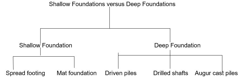
Foundations are aimed at safely transferring the load of a structure to avoid excessive settlements or to avoid bearing capacity failure. There are two main types of foundations namely shallow foundation and deep foundation. The choice of a type of a foundation is determined by the conditions of the subsoil and the structure of the load (Das, 2011).
Shallow Foundation
This is the most common structural foundation in the modern world of construction; the use of shallow foundations saves up to fifty percent of the overall costs of foundation. Shallow foundations are often chosen when the subsoil conditions can be found at a shallow depth or when the load of the superstructure design is not sufficient enough to demand deep foundations. Shallow foundation requires long term settlement, bearing capacity and it should as well be designed to withstand the strong effects of the thermal balance between the ground and the structure. Examples of shallow foundations are spread footing and mat foundations. Shallow foundations have greater depth of embedment-to-width ratio which is less than four.
Deep Foundation
This is commonly used in bridges due to its greater trust. Examples of deep foundations are drilled shaft foundation and pile foundation. Deep foundation has its whole depth of embedment-to-width ratio being more than four (Das, 2011).
These two main types of foundation and their subdivisions can be diagrammatically summarized in the following diagram.
Raft foundation, which is also called mat foundation, is considered a form of a combined footing that can cover an entire area under a structure that supports various columns and walls. Raft foundation is at times preferably used for those soils that have low loading and bearing capacity but only those which support high column and wall loads. Under certain circumstances, spread footing should cover half of the building area and in this case mat foundation is economical (Das, 2011).
Mat Foundation
Under normal conditions, rectangular and square footings are considered only to be economical in walls and columns but under special circumstances, it is recommended to construct footings that support two or more columns; these footings are called combined footings and when only a line of the column is supported by one concrete it is referred as a mat foundation (Das, 2011).
Mat foundation, otherwise called raft foundation is a large footing which extends over a large area, on many occasions the whole building. In mat foundation, all the structural loadings from the walls and the columns are supported by the common foundation. In this type of foundation, the mat can be utilized in such circumstances where the preliminary design shows that individual footings or columns would be close and might overlap. Mat is constantly used to distribute or in the reduction of differential settlement between the adjacent sites. For the mat to function properly, its structure must be thicker and rigid than the spread footing. This type of foundation is only applicable in circumstances where the conditions of the soil are weak and poor. Mat foundation is made up of large slabs of concrete and beam system resting on the rock and supports several columns and walls. It is a necessity that while adopting raft foundation care should be exercised to understand whether there are cracks or weak posts beyond the foundation. It is a common practice that raft foundation should be used over the piles to minimize settlements and in this case only a small portion of the load is taken by piles (Das, 2011).
Mat foundation is the large slab of concrete that is often used to interface one or more than one column within the same base soil. Mat foundation can encompass whole or a section of the foundation. Mat may also be used in supporting an on grade storage or several pieces of industrial equipment; they may also be used beneath clusters of silo or any other structure. Mat foundation may be used in situations where the base soils have low capacity of bearing and where the column loads occupy more than fifty percent of the area covered by the spread footing. Mat foundations can also be used in deep basements to spread the column loads to a more uniform pressure distribution and in providing the floor slab for basement. Based on costs, mat foundations require positive as well as negative reinforcing steel. In situations of high groundwater or where the soil is susceptible to large settlements, mat foundations can be supported by piles to control buoyancy (Das, 2011).
Types of Mat Foundation
Various types of mat foundations are used nowadays but the most common is that which is made of concrete slab with two reinforcing top and bottom:
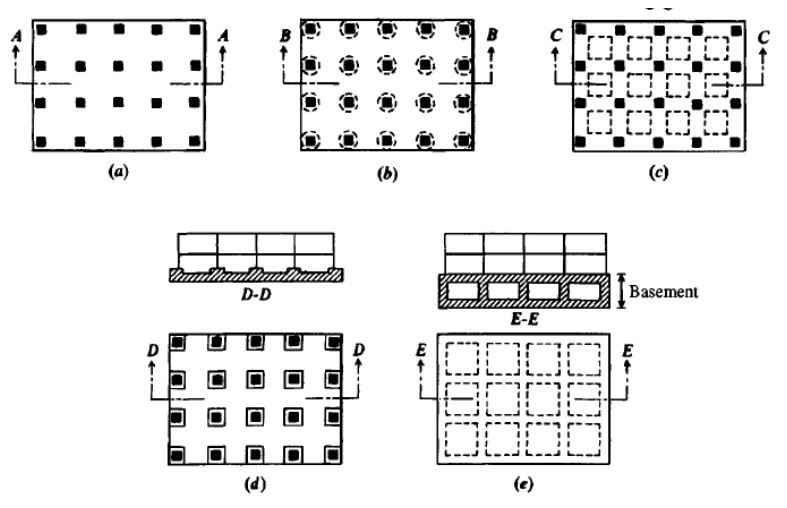
- Flat concrete plate where the mat is of uniform thickness: These are flat concrete slabs that might or might not have pedestals. This is demonstrated by the diagrams below
- Slab thickened under larger column loads
- Beams and slabs: This is where the beam runs in both ways and the columns are located at the point of intersection of the beams. These have down standing or upstanding beam and because of the difficulties in building and the hazards in construction, the up stand beams that are mixed with compacted granular materials and covered with mass concrete are the most popular beams than the down standing beams. There are also stiffened edge raft that has peripheral down stand or that which has a stepped down beam can as well be used as water ingress.
- Flat plates with pedestal. This is necessary to avoid differential settlement. This is only applicable to weak soils and can support heavy load columns.
- Slab with basement walls as part of the mat. This is aimed at reducing settlement in buildings.
The above types of mat foundation can be diagrammatically represented as shown below:
Mat foundations are overburdened by the following three factors:
- The additional costs of analysis which may not be exact
- The extra costs of overdesign which may only be reasonable if the element of the structure will be relatively small when compared with the total costs of the project.
- Extra safety margin which contributes to costs
Combined Footings
Combined footings can be classified into the following three categories: rectangular combine footing, trapezoidal combined footings and strap footing.
In rectangular combined footings, the load that can be carried out by the column and the bearing capacity of the soil are spread in such a manner that the standard spread of the footing requires the extension of the column foundation beyond the line of the property. Trapezoidal building on the other hand can be used at times as an isolated spread foundation of various columns that carry large loads in a place where the space is tight. In this footing, the size of the foundation can uniformly distribute pressure on the soil. Strap footing is also called cantilever footing and it can be used to connect an eccentrically loaded column foundation on the foundation of any interior column (Das, 2011).
Bearing Capacity of Mat Foundation
The mechanism of a bearing capacity failure of mat foundation is the same as that of the footings except that mat foundation involves a deeper and bigger zone of failure. The ultimate bearing capacity of mat foundation is provided by similar expressions just as those of the footing. Terzaghi’s equation on strip footing can be applied in the determination of the soil bearing capacity in raft foundation.
Mat foundations might only be designed as a measure to limit settlements to a containable amount. The settlements may include:
- Consolidation. This includes secondary effects
- Immediate or elastic
- Mixture of consolidation and immediate amounts
Any mat has to be stable against a shear failure and it may result in a rotational failure which can be typified by the Transcona elevator failure or even vertical failure. In various occasions, a uniform vertical punching failure may not be that serious since the effect would be just a large settlement which can be landscaped. This is irrespective of the fact that the settlement may not likely be uniform as expected. This should be treated with a lot of concern that is the same as deep seated shear failure.
Bearing Pressure of Mat Foundation
The recognized bearing pressure for the foundation materials should be assessed by determining the exposures and rock cores. The bearing pressure improvement factor is considered as the ratio of the bearing pressure of the improved ground and that of the unimproved ground at the given displacement. Consequently, the settlement improvement factor is that ratio of the settlement of improved and unimproved ground at the given pressure. Goods performing footings produce maximum pressure (Das, 2011).
Differential Settlement of Mats
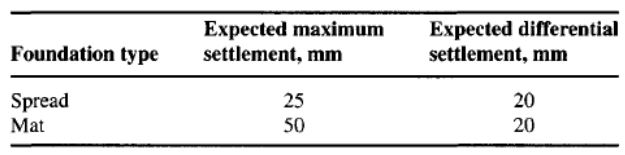
Mat foundations are only used in places where settlements may be a problem such as places with erratic deposits or places with lenses of materials that are compressible or suspended boulders. These settlements tend to be controlled in the following manner. First is through the use of large foundations as a measure of producing lower contact pressures of the soil and secondly through displaced volume of the soil or rather floatation effect; this is in the event the weight of the excavation will be equal to the weight of the structure and mat combined. This will make the system to float in the soil and hence there will be no settlement. The settlement can also be controlled through bridging the effects that are attributed to the rigidity of the mat and in contribution of the rigidity of the mat superstructure. It may as well be controlled by allowing larger settlements like 50 mm instead of 25 mm (Coduto, 2001).
In this situation, the flotation effect should play the role of enabling various mat settlements even in circumstances where consolidation is a problem or when piles are used to be within the limit of 50 or 80mm. Differential settlement is a major problem of mat foundation and the mat will tend to minimize this value. The continuity of the mat can result in a lower assumed quantity of differential settlement which might be relative to the whole expected settlement rated against spread footing as shown below.
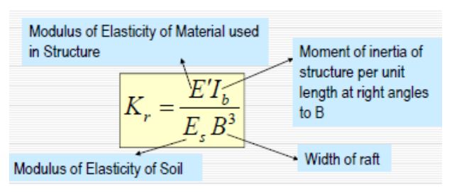
By using computer methods to incorporate the foundation of frame interaction, one may be able to estimate the differential and the total settlements. This is because the total settlements can only be the same as the soil data and if any other strip from the mat is used in beam-on-elastic foundation form of analysis, the methods of computing will be important. Computation wise, differential settlement can be arbitrarily taken as 20mm if the anticipated settlement is more than 50mm; this may also be approximated using the rigidity factor which may be defined as follows:
Where
From the above computation it is evident that differential settlement is related to both the structure rigidity factor K and the total estimated foundationΔH. The key problem in the excavation of clay is the expansion and the lateral flow into the base of excavation; this will make the base elevation to rise. This is what is called heave and it measures 25 to 50mm, it is always hard to compute settlements of mat after an occurrence of heave and hence the heave should be recovered after the reapplication of the mat pressure that is equal to the previous one (Coduto, 2001).
Compensated Foundation
This is the situation where the net pressure in the soil is increased in depth under mat foundation. This can be extremely useful when the structure is constructed on clay soils. Under compensated foundation design, the basement is made to appear below the higher portion of the superstructure to allow for the uniform increase in the soil pressure at any depth.
Structural Design of Mat Foundation
For any successful raft design, raft layout should be carried by paying attention to both the bearing capacity and settlements. In the flat slab analogy for example, it had been used successfully several times but had led to structural failures due to inability to understand the basics. In this analogy, it is evident that small deflection can only be acceptable in circumstances where the differential settlements between columns are small. In circumstances where differential settlements are large, a fresh slab analysis will indubitably produce satisfactory results. The following are the two main approaches that are used for the design of the slabs: the rigid foundation approach and the flexible foundation approach. The design of mat foundation can be done through the following ways (Coduto, 2001).
Settlement analysis which is aimed at achieving the deformation of the slab and two is for the compression of the beneath soil and the differential settlement of the raft foundation which was developed by the American Concrete Institute committee of 1988. The analysis of raft design via the differential settlement of mat foundation can be realized through the following method.
In the case of rigid foundation approach, there is the assumption that the raft is rigid and the assumption that the pressure distribution varies linearly or is uniform. Rigid raft is designed particularly as a floor system and also as a series of combined footings. And in both cases it is the bearing capacity of the soil that is factored into considerations.
The flexible approach on the other hand has two models namely the Winker model and the elastic half space model. In this approach, the design of the raft may be done in form of single system by using sophisticated software such as the finite element model or can be analyzed through the use of series of beams on an elastic foundation. Through winker model, the flexible approach takes into consideration the rigidities of the structure and that of the soil.
There are several methods of designing mat, these are:
- Approximate method: this is where the mat is divided into strips that are loaded by several lines of columns and which are resisted by soil pressure. This is analyzed as a combined footing. The approximate method can be utilized in places where the mat is rigid and where the column pattern is uniform in load and space. This method is not appropriate at the present due to the substantial amount of approximation and the wide availability of computer programs which are easy for use especially the finite-grid method. Mat is considered to be very expensive and not appropriate in circumstances where there are refined methods of analysis available.
- Approximate flexible method: this was the method which was suggested by the ACI committee in 1988 and when it is used, it should be programmed based on the AIRPAVE computer program. This method calls for the following steps in analyzing:
- Computing of the plate rigidity
- Computing the radius of the effective stiffness
- Computing of the tangential and the radial shear, moments and deflection by use of the following equation:
During the computing, tangential and the radial moments in the polar coordinates at the point of loading should be converted to rectangular coordinates and referenced to the origin by the use of transfer equation and for the various loads at the region of influence the values of the moments are added but by paying attention to the plate design. When the edge of the mat falls within the influence radius; the edge moment should be calculated and not the shear and the parallel edge moment and the shear are then applied as the edge loads but with opposite site.
- Rigid method: this applies in situations where the mat is very rigid and the contact pressure is planar. It utilizes similar assumptions that are used in the4 design of spread footing.
- Discrete element method: This method involves division of the mat into several elements by gridding. These methods include:
- Finite difference method: this utilizes the fourth order differential equation that is found in the text and the theory of shells and plates. This is computed as follows.

Advantages of the finite-difference method
- It is the commonly used method and hence acts as an alternative check on other methods
- It is reliable especially if the mat is modeled through finite-grid method
- It is rapid because the input data is minimal when juxtaposed with other methods.
- The computations to built array of stiffness are not very extensive since only three or five lines of input data are needed.
Disadvantages of the finite-difference method
- It is very difficult to model boundary conditions of column fixity using this method.
- It is hard to model reentrant corners, holes and notches
- It is also difficult to apply concentrated moment because different models use different width.
Flexible approach method
The analysis of the costs of raft foundation is only a minimum for the conventional rigid and combined approach and it increases when various factors are taken into consideration. It would only be only maximum when it is undertaken in a computer utilizing flexible approach while taking into account all the forces that the building can be subjected to, raft rigidity and soil interaction. Flexible approach utilizes the elastic properties of the soil and the accuracy of flexible approach depends on the accuracy of the soil. This approach is only adopted when the soil load adopted are lower when compared to its bearing capacity. This approach is based on analytical linear elastic solutions. This approach is based on closed form solutions for the Winkler kind of elastic space.
Finite-element method (FEM): this method involves the maintenance of element continuity by the use of displacement method. This displacement function is the following form:

With displacement of the regular plate and other three of the corner node, only twelve unknowns are needed which will result in reduction of the general equation of the displacement. The three engineering displacement at each corner will best serve to discard a heavy task that comes with both computational ability and engineering judgment. The finite element method was proposed as the best procedure that can reduce and also solve resultant matrix. The progress made in the Finite-element matrix is the use of isoperimetric formulation element which implies that a given element can have more nodes than the adjacent element. It is always very difficult to interpret the output of FEM, this is because the method is computationally very intensive and also its general methodology applies advanced concepts of mathematics which various structural and civil engineers are not conversant with it. This method also has the problem of unit incompatibility hence making summation impossible. In this method, vertical force summation is not possible because the shears of the element node are very hard to compute. FEM is not recommended format and plate problems; though it has several suiting design situation, FGM is preferred for more direct solutions for foundation engineering problems.
Finite-grid method (FGM): this method is the best in the analysis of mats and plates. It has the following merits:
- It is easy to interpret the output because the beam-column elements with bending and torsion are used. The unit width or the moment is considered as the node moment and it is divided by the element width.
- Obtaining design shears is very easy especially at the end of the element. This is because the shear will be considered as the sum of the element-end moments that is divided by the length of the element. One can also divide the sum of element shear by the width of the element to obtain the shear or the unit width.
- With this method it is very easy to compute the concentrated column moments directly.
- Also boundary cases can be easily modeled with this method.
- With this method it is very simple and possible to extent three degrees of freedom nodes of this method and use six degree of freedom which is suitable for pile gap analysis.
FGM method is similar to beam finite element method but it is extended to the beam column and used for a plate.
Mat-superstructure Interaction
The performance of the raft together with rigidity of the superstructure is highly dependent on the connection between the superstructure and the mat. In superstructures like silos and oil tanks, the rigidity of the world plays a crucial part but in buildings it has been observed that rudimentary approach is enough to take care of the superstructure rigidity. For structures that are flexible with a lot of columns that are spaced and few building walls between superstructure and the mat, the effect of the superstructure can either be ignored or it can be added into the mat slab arbitrarily.
Structural behavior of mat foundation
The elastic deformation of the continuous reinforcement of the concrete slab in the both directions as well as the nature of the stiffness of the slab makes it easy to transmit the columns of loads and share them equally along the all area of the foundation. This will provide a bridging action over the weak spot in the supporting soil and it might result in a sufficient contact pressure within the bearing capacity of the soil. Mat foundation is applied during the construction of basement substructures of powerhouses and office buildings.
Superstructure rigidity can be considered as problem just as it was demonstrated when it was done in semi empirical manner by using FGM which required substantial amount of computation. Regular frame analysis may be used in the analysis program and add a beam–on elastic foundation subroutine to the global ASA matrix nodes for the frame as well as for the foundation. There are very few computer programs to be able to do superstructure foundation due to the ease of banding any frame program that can separate a narrow bandwidth of a beam–on–elastic foundation. In the event where both superstructure and the foundation are included, the band with may enlarge but this may not be a problem because modern computers can handle large array of stiffness. The major solutions to superstructure problem include the following:
- Code and analyze the superstructure to obtain axial column forces and also to obtain applicable column base bending moment. This implies that fixed base condition should be assumed.
- Code the mat or combined footing with the nodes found at the superstructure column. The output of the above step can be sued as the input of this second step to arrive at solution. This will result in node vertical translation and the rotations of the nodes of columns.
- The data from the above second step can be used as boundary conditions for the rerun of the first step above, this will serve the purpose of specifying the rotations of one of the columns and vertical displacement. This will result in new set of axial forces and moments.
- The above steps should be iterated until when the axial moments and forces fall within certain level of tolerance to the preceding cycle. Having reached this point one will have a reasonable and a better solution for both the foundation and the superstructure (Rochester Institute of Technology, 2008).
Conclusion
Raft or mat foundation is a combined footing which covers an area that is beneath a structure. In building structure, when the pressure allowed is low or in the event the building load is heavy, suing spread footing which is a form of deep foundation which might cover a very large area might prove to be economical to sue raft foundation. Raft foundation is widely used because it is economical and it is applicable in situation where the soil has a lot of compressible lenses or if the soil is very erratic to the extent that differential settlement might not be easily controlled. It is the raft which bridges these erratic deposits and it is also the raft which eliminates differential settlement. Raft foundation is required to minimize this settlement in the high compressible soils by equalizing the weight of the structure and that of the soil that is excavated.
The real raft foundation should be made up of concrete or slab that is of uniform thickness throughout. This kind of foundation is only adopted when the column spacing is minimal and when the loads of the column are small. Raft foundation directly rests on the rock but it may also rest in piles. The substructure distributes loads of columns and walls of superstructure over the entire area of foundation through a continuous slab. Mat foundation is also called float or raft foundation because it acts as a raft that can spread concentrated and unequal column loads over a very large area of the foundation soil that can support the loads.mat foundation is applicable where the geotechnical properties of the soil very even in short distances or where the bearing capacity of the soil is poor. There are at times when constructors spread footing for the column load until it becomes large hence forcing it to coincide with the footings adjoining it also at times the unequal loadings per column in the structure and the bearing pressure variation within the substructure, the spreading can vary, to overcome these unnecessary variations, mat foundation should be adopted.
References
Coduto, D. P. (2001). Foundation design: Principles and practices. Upper Saddle River, NJ.: Prentice Hall.
Das, B. M. (2011). Principles of foundation engineering. Stanford, CT: Cengage Learning.
Rochester Institute of Technology. (2008). Student life center. Rochester, NY: Rochester Institute.