Introduction
In pile foundations, pile cap families are used; the pile cap families are shipped with the Revit structure. Pile foundation may be simply considered as a structure supported by piles. Pile foundation is applicable in environments where the circumstances of the soil are not good. Pile foundation provides for any form of structure to be sustained. The two types of pile foundations are pile and pile cap. Pile foundations are the sections of a building that are used in transferring the weight to the ground. Pile foundation is applied in the lowering of the foundation into the soil. Pile foundation is often steeper and stronger. The load capacity of the pile emanates from the shaft friction and the base resistance. Driven piles can be considered as either non-displacement or displacement piles (Das, 2011).
Piles
Piles are defined as structural columns that are installed on the earth so as to provide support or to aid in the resistance of forces. The most common form of pile is the driven pile which is considered to be long and slender and is used in providing support and in the resisting of forces. Driven piles are made of preformed material and they have a predetermined shape and size which can be inspected physically prior to and during the installation. Driven piles are installed by the use of vibration; impact hammering and it can also be pushed into the earth.
Displacement piles are available in a solid shape during installation and have the ability to displace the soil laterally. Non-displacement soil on the other hand is of hollow and outlines shape and can only displace littler or no soil during installation (Das, 2011).
Drilled pile on the other hand is made of concrete and cast and often available in plastic state that can be placed on the drilled hole on earth. The various forms of drilled piles are drilled shafts, augercast and drilled cast in place together with all their variations of drilled piles. Drilled piles that are completed can not be inspected easily after installations; it is also very difficult to install it on soft, loose wet or marine soil conditions. Drilled pile has the capacity to remove soil from the ground and the round hole from it can be filled via grout or concrete. This is unlike driven pile which is installed as a whole or structure member into the ground surface (Das, 2011).
Piles are available in different shapes and sizes they are low-priced and cost effective in various regions: “Piles are long and slender members which transfer the load to deeper soil or rock of high bearing capacity avoiding shallow soil of low bearing capacity” (Das, 2011, p. 1). Piles that are completed from the above materials are “drilled, driven or jacked into the ground and then it is connected to the pile caps” (Das, 2011, p. 1). Piles may be driven or pushed into the ground or in concrete piles that that may be cast in situ through the pouring of concrete into the hole that is dreamed. In the analysis of the piles, it is assumed that the weight of the pile is equivalent to that of the ground that is displaced and hence both are neglected. Pile foundation is preferred in the following circumstances:
- When the load of the superstructure is very heavy and its distribution is uneven
- When the bearing capacity of the top soil is poor
- If the water level of the sub soil is high that it can pump water from the open trenches; this is because shallow foundations is uneconomical and difficult
- When there is a large fluctuation in the water level of the subsoil
- In the event strip foundation is attempted; this makes the timbering of the sides to be hard to maintain or to retain the soil sides of the trench.
- If the structure is located in the sea shoe or along the river bed
- If the nature of the top soil is expansive
History of Driven Piles
Driven piles are considered to be as old as history and they have been in use since the Neolithic period people who dwelt on the lake sides particularly in eastern France, Switzerland and Austria constructed their houses and villages by use of driven piles which were supported by defensive measures. Barbaric civilizations have been using driven piles as well as poles to support their homes in flood prone areas while others have been building it on driven piles by filling it with stone and build bridges. The equipments that is used in driving piles have evolving since the early stages. With the advent of new technology al information from the understanding of the soil properties to site investigation ate easily available to the engineers and hence this makes it very easy for them to understand various characteristics and the load carrying capacity of the various types of piles and the engineers can achieve this with high degree of accuracy before even designing the structure (Das, 2011).
A greater efficiency in the selection of pile types can be realized through the understanding of the strength and the performance of the pile materials. Modern equipments have been utilized in the installation of driven piles this includes the Global Positioning Systems which assist in the survey of pile locations. Hammers can be utilized in energy adjustments and in the monitoring so as to guarantee the needed hammer performance and to protect the piles from any form of damage. There are instruments which can be used in the testing and the installation and the confirmation of the pile load capabilities. There have also been developed some testing techniques that are available and can be used in the checking of performance from the previous driven piles and they can be used to compare them to the demands for the specification (Das, 2011).
Materials for Making Piles
The common materials that are used in making piles are concrete, timber, composite and steel. Timber concrete and steel are often considered to be traditional and are the most common types while composite have their place. Composite piles are commonly used in marine environment; this is because marine environment has adverse effects on timber, concrete and steel (Coduto, 2001).
Types of Piles
The using of files as a foundation can be traced to the old days of the Roman Empire. Pile foundation is considered to be the common type of deep foundations. Piles can be classified based on the functions ands also based on material and composition.
Classification based on functions
The classification of piles according to the uses is: end bearing pile, compaction pile, friction pile, tension pile, fender pile, anchor pile, sheet pile and batter pile.
End bearing pile: these are the types of piles that are used to transfer load through soft soil or water to a bearing stratum that is suitable. They are applied in hard and in Impenetrable materials like rock gravel or dense sand. End bearing piles derive much of their carrying capacity from the stratum resistance that is placed at the toe of the pile (Coduto, 2001).
Frictions piles: These are the types of piles that are used to transfer loads to a friction depth load that carries materials through skin friction and through pile length. Much of the carrying capacity of friction piles is via adhesion or skin friction: This tends to occur when piles do not reach an impenetrable stratum but are driven for some distance into a penetrable soil (Coduto, 2001, p. 1). The carrying capacity of friction piles is obtained from end bearing and partially from skin friction that happens between embedded soil surface and the soil in the surrounding (Coduto, 2001).
Compaction piles: this type of pile is used for compacting loose granular soil hence increasing their bearing capacity. The compactions piles don’t carry any load since they may be made up of weaker materials at times made of sand. The pile tube that is driven to compact the soils is taken out gradually and the sand is filled to replace it hence forming a sand pile (Coduto, 2001).
Uplift or tension piles: this can anchors down the structures that have been subjected to uplift as a result of hydrostatic pressure or as a result of overturning moment: In the design of tension piles the effect of radial contraction of the pile must be taken into account as this can cause about a 10% – 20% reduction in shaft resistance (Coduto, 2001, p. 1).
Anchor piles: this serves to provide anchorage against the horizontal pull resulting from sheet piles or any other pilling pulling forces.
Dolphins and fender piles: These are used in protection of water front structures against any impact from floating objects or ships.
Sheet piles: sheet piles are used as bulkheads; they may be used as well as impervious cut off in order to minimize seepage and to help in the uplifting of hydraulic pressure. Sheet piles are considered to be specialized forms of non-displacement that are formed in the sheets and which have connections on the edges to allow for interlocking with the adjacent piles. Composite and more of steel can also be utilized. It is noted that, “Sheet piles are unique in that they are designed to be joined with adjacent piles by the use of integral interlocks” (Das, 2011, p. 1). The most prominent form of light sheeting applications are the galvanized light gauge and aluminum sheet piles (Das, 2011). This is because they provide advantage of resistance to corrosion in bulkhead applications. The diagram of sheet piles is as illustrated below.
Batter piles: batter piles are used in resisting large inclined or horizontal forces.
Classification based on compositions and materials
Concrete piles: the categories of concrete piles are precast, cast in situ. Cast-in-situ can be categorized into driven piles which may be cast and uncased and another category is bored piles which includes pressure piles and under-reamed piles.
Synthetic piles: These have gained prominence in the recent period and include use of fiberglass, Vinyl and polymers; these types of piles are used in desperate or special applications. Vinyl sheets are specifically becoming a common application especially in the situations where lateral loads are not great and aesthetics is a factor. This is applicable in residential areas since the owner has a clean white wall at the edge of the water. On the other hand fiberglass that has reinforced plastic piles is used in applications in the event where resiliency is a factor. The following is an illustration of Vinyl sheet piles.

Timber piles: Timber as a material is considered to be cheaper than concrete and steel but its supply is slowly diminishing. Timber piles are light and easy to handle and readily be trimmed to desired length. Timber piles have a very low bearing capacity and are only temporary unless they are treated. Timber piles are vulnerable to damage particularly by hard driving and hence should not be driven through boulders or hard stratum. Timber piles are very light and can easily be handled. Timber piles can be easily joined together and it can also be provided with driving points. The main disadvantage with timber piles is that is vulnerable to decay and can easily be attacked by the marine bores hence are only used above the water surface. Timber piles are commonly used as friction piles and can only be applied on some circumstance as bearing piles. Timber piles can also be made from tall tree trunks or trees that are straight. Timber piles that are untreated are only applicable during temporary situations while the top of the soil will often be below ground water level. All timber piles that are permanent are driven in environment that is Marine and in the event the butt will be in ground water level then a preservative treatment will be applied in order for it to resist marine borer and insect attack (Coduto, 2001). The most common types of timber are one made of untreated timber and covered with a metal shell that is filled with concrete and this is common in the USA where the ground water is considered to be within ten feet off the surface. Example of timber pile is illustrated by the diagrams below.
Steel piles: this can be classified into H-piles, sheet pile and pipe pile. Steel piles are often fixed on the cast in place concrete. Steel piles are used in situations where the length of the piles needed is longer than the needed cast in place type.
Pipe piles are often made of steel and come in different diameters. Pipe strength is often defined by the strength of the steel and thickness of the wall. In the circumstances where the bending resistance is needed, concrete is placed in the pile only after driving. Pipe piles can easily be spliced as a measure of extending the piles; this can be achieved though welding or though the use of mechanical connectors. Pile piles can be coated as a measure of protecting it from corrosion and a unique form of pipe pile is the steel pile. This will provide an additional load capacity and it will also increase the diameters.
Composite piles: this includes concrete and steel and concrete timber. This type of piles is only used in situations where the upper part of the pile is intended to project above water table. Composite piles have its lower portion of an untreated timbre and an upper portion that is made of concrete.
The precast concrete piles are used for the maximum design of approximately 80 tones but not for pre-pressed piles are large. Precast concrete piles should be reinforced to withstand and to handle stresses. Precast concrete piles requires space for storage and casting and it also requires more time to set and cure before the installation and it demands heavy equipment for driving and handling. Large costs are also incurred in the addition or cutting of extra length. The cast-in-situ piles can only be used for loads that have a maximum weight of 75 tones with the exception of compacted and pedestal piles. Various cast-in-situ piles that are in use all bear the name of the manufacturer and the common types of precast in piles are: the Raymond standard pile, Union metal pile of monotube, Frankie standard pile, MacArthur cased pile, MacArthur compressed uncased pile and Raymond Step-tape pile. The following is the diagrams of solid precast concrete which is of displacement pile category.
Under reamed pile: this is one of the special types of bored pile that has an increased diameter and a bulb at a certain point in its length; this is mainly aimed at anchoring the foundation in an expansive soil that can be subjected to contraction or alternate expansion.
Concrete filled steel piles: this are utilized as long piles with a bearing capacity that is high. These types of piles are seldom used unless the bearing capacity reaches a stratum of a high supporting capacity; this is because it is costly. Concrete piles are manufactured in hollow or solid form or also in square, octagonal or a round cross-section. In the modern form of manufacturing, pre-stressing technique is employed and it helps in increasing the resistance to bending and also it helps in minimizing the amount internal steel reinforcement that is needed. Due to its inherent resistance to corrosion, concrete piles are considered as a perfect material for marine application. An example of concrete pile is illustrated by the diagram below.
Drilled piles are installed through the drilling of a hole on the ground by use of an augur. A grout or a concrete is laced on the hole and this forms the pile. An example of anchored cast in installation is indicated by the diagram below.
The following is a diagram of drilled shaft installation
On the other hand driven piles are installed using a vibro driver, an impact hammer or a hydraulic press; the performance of driven piles is closely monitored during operation. Driven pile equipment that is modern is capable of providing a consistent and more energy that is needed during the operation. In this case the advancement of the pile into the earth can be monitored and recorded for further study. Driven pile is a predetermined solid material of shape and sixe that can be felt, seen and that which can be inspected before installation and that it can be installed via pushing or driving into the earth. There are various types of structural use and they are categorized based on the following: their resistance to vertical compressive forces, their resistance to lateral forces and their resistance to the tension forces.
Concerning resistance to vertical compressive forces, the anticipated support should have resistance to vertical loads like docks, tanks, towers and bridges. This is as demonstrated in the following diagram.
Regarding resistance to lateral forces, this concerns the forces that are supported from the inside laterally and includes the sheet piles, fending and mooring piles and other piles in the same situation. Concerning tension forces; this concerns the ability of the piles to counteract wind or to overturn loads; this will result in the opposing of buoyancy, floatation forces and an illustration is indicated by the following diagram.

Driven piles can too be displacement or non-displacement. Displacement piles have a solid shape while non-displacement piles have a shape that is hollow or outline (PDCA, 2003).
Uses of Piles
A pile foundation is significant in “transmitting a foundation load to a solid ground to resist vertical, lateral and uplift load” (PDCA, 2003, p. 1). Any structure can be founded on piles is the spoil is beneath its base and lacks bearing capacity that is adequate. In addition, “If the results of site investigation show that the shallow soil is unstable and weak or if the magnitude of the estimated settlement is not acceptable a pile foundation may become considered” (PDCA, 2003, p.1). When costs are analyzed, piles may be appropriate since they are considered to be cheaper when compared to other types of foundations that demand much costs for ground investment. Consequently it is noted that “in the cases of heavy constructions, it is likely that the bearing capacity of the shallow soil will not be satisfactory, and the construction should be built on pile foundations” (PDCA, 2003, p. 1). Principally piles are used in the transferring of loads to a stiffer or to soils that are strong in order to enhance the effective size of the foundation as well as to resist horizontal timber loads (PDCA, 2003).
Pile Driving
Piles are often driven by use of hammer; this hammer is in various occasions supported by the crane or by a pile driver which is a special device. The hammer is guided between two leads which are parallel. These leads are carried by a frame in a manner that they are supported in a vertical or an inclined position (PDCA, 2003).
Pile Installation Techniques and Equipment
Pile installation techniques and equipment there are various tools that are used in the actual driving of piles and this includes: impact hammers, vibratory extractors, special hydraulic presses and supporting equipment (PDCA, 2003).
Impact hammers are simple and they advance the pile on the soil by rising by raising the weight until they are allowed to roll or to be accelerated downwards in order to strike the pile and to drive it downwards. Impact hammers have attachment at the top of the pile and the lower base. The following are the various types of hammers and their illustrative diagrams (PDCA, 2003).
Air hammers

Diesel hammers

(PDCA, 2003)
Hydraulic impact hammers
The following are the various diagrams of vibro driver or extractors
There are also the hydraulic press installers which utilize reactive resistance so as to be able to anchor hydraulically operated jacking system which can push the piles into the ground. This reactive resistance can either be from temporary or adjacent piles installed previously and functioning in tension. Hydraulic power utilizes power pack for motive power. The following is the diagram of hydraulic press installer (PDCA, 2003).
Pile Caps
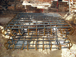
Pile defined as structural elements that tile various piles together and they are intended at supporting bearing walls, isolated columns or various groups of columns. Pile caps are utilized in transmitting forces from the walls or columns to the piles. The plan dimension of pile caps can be based the allowable and closest space of the piles which is approximately 1m and its depth is based on the shear or the development length of the column bars. The pile cap with the pedestal should be paced or rather kept deep enough so as to provide for necessary anchorage of pile and column reinforcement. The clear over hang of the pile cap that is beyond the outermost pile should be approximately 10-15cm. the labeling of the mass concrete of thickness 8cm is always provided under the pile cap.
Pile cap is defined as “A pile cap is a thick concrete mat that rests on concrete or timber piles that have been driven into soft or unstable ground to provide a suitable stable foundation” (PDCA, 2003, p. 1). Pile cap forms part of the foundations particularly those of storey houses in order to support the heavy constructions equipments. The concrete piles distribute into piles all the load of the building. It is a reinforced concrete slab that is constructed at the top of several foundation piles so as to spread or displace the load that they carry. Pile caps can also be sued in reference to glass or plastic fiber that is placed on the top of wooden pilings. The following diagram is an illustration of a pile cap (Das, 2011).
Uses of Pile Caps
Pile caps are primarily used in the supporting of bulk handling plant. They are considered to be the concrete base that supports the machine engine of the pile during construction. Pile caps support the imposed load and it should be spread equally in the pile surface and between the piles.
Advantages and disadvantages of using piles in weak soils
In soft soils there are high chances that the pile cap may not be in position to dominate lateral stiffness provided for by the foundation just would have been the case in competent soils. This might result in lateral displacements in the event the capacities are mobilized during lateral loading. In the case of weak soils the piles are designed in a manner that will accommodate the axial forces and the head moments. The greatest disadvantage in the case of weak soils is that the resistance that is developed by the pile cap and the lateral shear resistance of the piles are usually very low (PDCA, 2003).
Other advantages of using piles on weak soils are: construction on the sand column is relatively fast; second is that a column constructed on weak oils is considerably cheaper when it is compared with stone and third is that the hole is usually supported by a casing during the construction hence this protects the holes from collapsing. Consequently the possibility of erosion or intrusion is often minimized as compared to stone columns (PDCA, 2003).
The disadvantages are: since it is weak soils, the column will have a lower angle of internal friction and stiffness of stone columns hence there is a high chance of replacement. Also driving the casing will minimize smear along the boundaries of the column hence reducing the lateral permeability thus minimizing the effectiveness of the drain (Coduto, 2001).
Conclusion
Piles are a form of deep foundation; piles are structural elements that are made of timber, steel, composite and concrete and are slender in shape. Piles are commonly circular in cross section but also hexagonal, square and octagonal sections are always common among precast piles made of concrete. Piles that are made of steel can be 1-section and often driven into the ground. There is also a pile group that is made up of two or more piles which are placed under similar cap and share a common column load. In many circumstance, piles are used when the column loads are too high especially in high rise buildings or it can be used for pad footing or in the event the soils beneath are weak. Piles carry their loads through the top and the shaft but in case the load is carried by the shaft they are referred as friction piles and when the load is carried by the tip they are referred as en-bearing piles. Piles can be utilized in resisting uplift forces on the foundation.
References
Coduto, D. P. (2001). Foundation design: Principles and practices. Upper Saddle River, NJ: Prentice Hall.
Das, B. M. (2011). Principles of foundation engineering. Stamford, CT: Cengage Learning.
PDCA. (2003). Driven piles are tested piles. Boulder, CO: PDCA.