Abstract
Because of the increasing number of terrorism activities, the human safety has become one of the most crucial concerns. This project aims at designing a robotic car system controlled by a computer via RF (400 MHz) signals. The robot can be controlled in several ways, with movements going up to 100m. The system is able to move the robot forward, backward, turn it left, right, and control its speed. The robot has a vision component that uses a “live webcam” to record happenings in its surroundings hence, providing a mechanism of detecting potential security threats, for example, explosives. In developing the system, a microcontroller was used to provide a strong base for developing the desired program, which is the main instrument used to control the robot and give it powerful video facilities for the graphic user interface (GUI). The analysis, design, and implementation of this robotic car system has been successfully completed and documented.
Introduction
The robotic car system has been implemented to ensure high levels of human security, in case of any security threats. It is better for people to avoid entering places with potential security threats, for example, explosives and radioactive materials hence, making it necessary for there to be a mechanism of detecting or people who can detect such threats. Considering the dangerous nature of this job, a robotic car will be handy for these kinds of endeavours and even more.
The mechanical structure of the robot’s body is based on an off the shelf electric car, whose use will be only along the motor and wheels. The control system will be via a PIC microcontroller, which will offer its user an opportunity of controlling the direction, movements, and velocity of the car. in addition, a camera will be installed on top of the car for provision of a line stream video necessary for detecting obstacles hence, offer a feedback to the controller about its exact position.
The primary component of this project is the PIC microcontroller, as it gives the required I/O, which is the main robotic car’s navigational component. Using the serial Pulse Width Modulation (PWM) by determining the control logic signals transmitted by the transceiver, the system will be able to control the direction and speed of the robot. To cater for current shortages from the microcontroller, an H-bridge will be used to supply current required to drive the motor; hence, functioning an interface between the PIC and the motor to execute all commands from the microcontroller
The main function of the wireless video will be to monitor the movements of the robot within a distance of 100 metres around the computer; hence, offering an easy mechanism of monitoring and navigating the car. The camera has a night-vision capability view hence, making it possible for the robot to go through dark alleys where the availability of light might not be important, but visibility is still crucial. Further, the system will have the capability. The system will have the capability of radio frequency communication (RF) that allows the user to control the car using devices with RF communication capability such as computers and handheld remote controls.
System Architecture
The robot system is comprised of small subsystems called modules. These are the primary mechanical components of the robot’s body, RF transceiver, power source, and the wireless camera. The system’s implementation methodology is generic, for purposes of flexibility in case need for future enhancement arises.
Mechanical Robot body
The mechanical structure of the robot’s body is based on an off shelf electric car, using only the car’s body, motor and wheels. The main control mechanism of the motor will be through the use a special PIC microcontroller, with the help of camera installed on top of the car.
The power supply
The design of the power supply is in such a way that, it is economical, provides an efficient operation methodology, and offers a high power rating. The system has been provided with two power supplies namely, an internal battery power source, and an external supply, which can be either the main or lab power supply (this will be taken care of once the control board of the root is tested and the motor’s power noted to ensure there is enough power. Additionally, there is a switch between the external battery sources, for purposes of offering room for isolation of the circuit in order to preserve power, in case such need arises in the future. Finally, the system has an LED for purposes of indicating the functionality of the power supply.
The Microcontroller
The microcontroller used in the system is PIC 16F877A. The PIC was chosen because it has the required I/O ports needed for complete communication and control of the primary components that work closely to fulfil the project’s primary goal. Additionally, the PIC gives a powerful base for developing the essential program for controlling the robot and giving powerful video facilities for the graphic user interface.
The primary functions to be controlled include:
- The speed and rotating angle of the front wheels
- The movement direction (forward, backward) of the robot
- The switching on and off the front and backlights, which are supporting lights for the camera
The key features provided by PIC 16F877A are two Pulse Width Modulation (PWM) units and two types of standard communication protocols RS232 and Synchronous Serial Port (SPI). These units are every crucial in navigating the robot.
Wireless Transceiver
The system is to use an easy-radio ER400TRS from TRS wireless transceiver, which integrates an easy-radio technology to give a high performance, and easy to use radio device. This device can bi-directionally transmit serial data over a range of up to 250 metres Line of Sight (LOS). Easy-radio has two primary features: firstly, the transceiver is simpatico with the RS232 protocol, because the preferred microcontroller is comprised of two protocols of inbuilt communication channels namely the RS232 and the SPI protocols. Secondly, the transceiver works on a 433 MHz frequency band and the wireless camera used functions best. To limit chances of interferences occurring between the two signals, it is advisable to use different frequencies for the wireless video transmission and the controlling wireless transceiver [9].
Wireless Camera
The camera is the main visual component of the robot, for it provides a mechanism of monitoring the robot’s movement and giving live video feedbacks to the PC (control unit) hence, helping in navigating the robotic car. The wireless camera has the following characteristics; it has a wireless capability, a night vision view (for dark scenario), and is self-powered. The separate power requires no power support from the main outlet; hence, it can be batteries or chargeable cells carried by the camera.
System Control
Controlling DC Motors
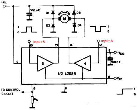
For one to control the motor to required levels hence, achieve the desired accuracy, one has to control two main parameters namely the speed and direction of the motor. To control the motor’s direction, one has to reverse the polarity, which can be altered by the control logic using the H-bridge (a main speed controlling unit). The H-Bridge helps in controlling the direction of movement and the speed of the motor depending on the need and commands given by the microcontroller, regardless of its direction (clockwise or anticlockwise.
Therefore, the L298 H-Bridge serves as an interface between PIC outputs and motors [3].
Direction control
To run the motor in a suitable direction, the two inputs (A and B) must be in a mode reverse to each other. Putting the motor in a halted state entails ensuring that the H-bridge has both the low and high signal at both the inputs of control pins. Therefore, one can control the motor in both directions by utilizing the logic in the H-Bridge.
Table 1. Truth Table to Represent the Bidirectional Movement.
The table below is of help in controlling the bidirectional movement of the DC motor, during the burning of this program in the PIC microcontroller. The microcontroller gives a low or high logic to the input of the H-Bridge control pins. Through having both pins of the motor suspended between four switches (BJT transistors), whose main role is to control the direction of the motor, the H-Bridge controls the angle orientation of the motor [5].
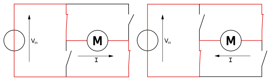
Through switching two of the switches ON, one transistor will open to the power, while the second one to the ground, the circuit will be complete hence, making the motor to rotate in the direction of the source current. Contrary to this, the direction of the motor will rotate to other directions when the other two transistors, which are OFF are turned ON, and those that are ON are turned OFF. Such change in directions are important in providing a mechanism of navigating the robotic car, as it determines the extent of the left and right turns.
Speed control
The primary DC motor speed regulator is the Pulse Width Modulation (PWM), which usually originates from the OPIC microcontroller. To change the DC Motor, one has to vary the width of the pulses; the broader the pulse width, the elevated the average voltage accepted by the motor, the shorter the pulse width, the lesser the voltage received by the motor. Therefore, the quantity of voltage receipt by the motor is directly proportional to the breadth of the pulses; hence, the primary determinant of the motor’s speed [10].
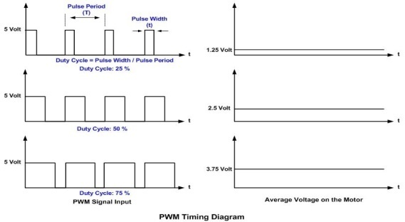
The duty cycle is the proportion of the pulse width to the overall length of the pulse; that is, [Ton/(Ton+Toff)]. This implies that, when 100% duty cycle is utilised, the motor will rotate at its highest speed. Equally, if the duty cycle is fifty percent, the speed of the motor will be half its maximum speed; hence, to stop the motor one has to reduce the pulse to zero reduce the duty cycle to 0% [2].
System integration
The project has two main subprojects, made up of software and hardware implementation. My colleague Saleh will design a Graphic User Interface on a PC (control unit), as the primary mechanism of controlling the proposed robotic car system. The final system design will consist of a robotic car that is to be controlled wirelessly via a computer with coverage of up to 100 meters. The Graphical User Interface (GUI) is designed to allow easy control with a simple view. This interface will allow the user to select the serial port for communicating, depending on where the wireless transceiver is connected. In addition, a live streaming feedback capability will be integrated in the GUI to assist the user to control the movement of the robot installed with a camera. Further, the driver is designed as a simple circle divided into 6 sections. Each section will have simple command to drive the robot. Each part will be given a different colour and name, whose main role is to help the user identify the function of each section. On the other hand, the colours will be used for the program, as a means of identifying sections to be pressed, in order for one to transmit the appropriate instructions to the robotic car
Result And Conclusion
Through using the required materials and observing the required standards, we were able to implement the project specifications successfully, as the robotic car formed responded to all commands. The robot moved to all direction swiftly as commanded and its lighting system worked as desired, as it was possible to turn them ON and OFF. The execution of all commands given from the control unit by the robot was a clear indication that the integration of the between the GUI and the Robot was successful.
The PCB of the robot was built using a portal program. The robot’s circuitry uses 6v and 25 MA, which can run the robot for one and half hours. The car is designed in a way that, once the car is stuck, the motor has to stop functioning hence, reducing chances of the motor burning. Finally, the robot test is to cover 100 meters, for within this zone the robot can receive all passed signals and execute them successfully.